EMC limits and test levels
Emissions
The radio frequency emission limits quoted in EMC standards are usually based on the level of disturbance that can be generated by an apparatus or system such that radio or TV reception in a co-located receiver is interference-free.
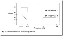
Conducted emission limits are set to control the disturbance voltage that can be impressed on the voltage supply shared by the source and receptor where coupling by conduction occurs. Limits currently applied in European emission standards are shown in Fig. 14.7. The Class A limits are appropriate for a commercial environment where coupling between source and receptor is weaker than in the residential environment, where the Class B limits apply. The difference in the limits reflects the difference in attenuation in the respective propagation paths.
The limits shown apply when using the ‘average’ detector of the measuring instrument, and are appropriate for measuring discrete frequency harmonic spectral line emissions. A ‘quasi-peak’ detector is employed to measure impulsive noise for which the limits are up to about 10 dB higher, i.e. more relaxed. The standards often require that the ‘average’ limit is met when using the ‘average’ detector, and the ‘quasi-peak’ limit is met using this ‘quasi-peak’ detector. Nearly all modern EMC measuring instrumentation contains provision for measuring using both detectors to the required degree of accuracy.
Typical limit levels are in the order of 1–2 mV for Class A and 0.2–0.6 mV for Class B. These are quite onerous requirements given that some devices, such as triacs for motor speed control may be switching a few hundred volts peak.
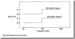
Radiated emission limits are derived from a knowledge of the field strength at the fringe of the service area, from typical signal to noise ratios for acceptable reception, and also from applying probability factors where appropriate. Typical limits are shown in Fig. 14.8.
Below 230 MHz the Class B limits are equivalent to a field strength of 30 µV/m at a distance of 10 m. Many items of information technology equipment have clock frequencies in the range 10–30 MHz, for which the harmonics in the ranges up to a hundred megahertz or more are effectively wanted signals, required to preserve the sharp edges of the digital waveform. This harmonic energy has to be contained within the apparatus by careful PCB design and layout and/or shielding and filtering.
Low-frequency limits for harmonic content are derived from the levels of disturbance that the supply networks can tolerate, and are expressed either as a percentage of the fundamental voltage or as a maximum current. Even harmonics are more strongly controlled than odd harmonics, since the even harmonics indicate the presence of a dc component. Similarly, flicker limits are set by assessing the effects on lighting of switching on and off heavy power loads, such as shower heaters.
Immunity
Immunity test levels are set to be representative of the electromagnetic environment in which the equipment is intended to operate. In European standards, two environments are considered, the residential, commercial and light industrial environment and the heavy industrial environment. The distinction between the two is not always clear but most equipment suppliers and manufacturers are knowledgeable on the range of dis- turbances that must be considered for their product to operate reliably in the field and can make the appropriate choice without difficulty. The key factor is whether heavy current switching and/or high-power radio frequency sources are present. If they are, the more severe ‘industry’ levels should be selected.
(a) Electrostatic discharge (ESD)
Electrostatic charge is built up on a person walking across a carpet or by other actions where electric charge separation can occur. The charge voltage is much higher for syn- thetic materials in dry atmospheres with low relative humidity. Although charge potentials in the order of 10–15 kV may be encountered in some environments such as hotels, the standards bodies have selected an air discharge level of 8 kV as being representative of a broad range of circumstances. The ESD event is very fast with a sharp edge having a rise time of about 1 ns and a duration of about 60 ns. This generates a spectrum which extends into the UHF bands and therefore presents a formidable test for many types of equipment.
(b) Electrical fast transients
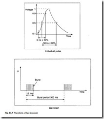
This is the disturbance type adopted by the standards bodies to be representative of the showering arc discharge encountered across opening relay contacts. Figure 14.9 shows the general waveform of the disturbance applied in the harmonized European standards. These transients are applied directly to the mains power conductor, or to inter- face and input/output cables via a capacitive coupling method to simulate the effects of co-located noisy power conductors. The voltage levels applied on the mains supply are 1 kV for the residential environment and 2 kV for the industrial environment.
(c) Radio Frequency (RF) fields
At low frequencies (below 80 MHz) the interaction of incident electromagnetic waves with receptor systems can be simulated effectively by a simple induced voltage impressed either with respect to ground via a network known as a CDN, or longitudinally via a transformer (bulk current injection). At higher frequencies (80–1000 MHz) the field is applied directly to the equipment under test, usually by setting up a calibrated transmitting antenna situated at a separation distance of about 3 m. The tests are performed in shielded enclosures in order that the RF energy can be controlled and no external interference occurs.
In the more recent standards, the walls of the screened rooms are lined with absorbing material to provide a reasonably uniform field within the chamber. The applied waveform is modulated with either a 1 kHz tone to simulate speech or a pulse train to represent digital cellular radio transmission.
(d) Dips, surges and voltage interruptions
Many other types of disturbances are present in the environment. These are the slow- speed types which are usually associated with power switching, lightning pulses and power failure. They are usually simulated by specialist disturbance generators. In many cases, immunity to these disturbances is achieved by good design of the mains power supply in the equipment under test. This is discussed fully in section 14.1.5.2.
(e) Magnetic fields
Equipment containing devices sensitive to magnetic fields should be subjected to power frequency (50 Hz) magnetic fields. Typical levels are 3 A/m for the residential, commercial and light industrial environment and 30 A/m in the more severe industrial environment.


