Cables
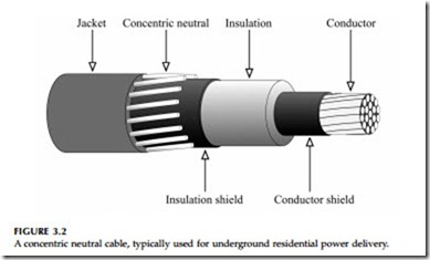
At the center of a cable is the phase conductor, then comes a semiconducting conductor shield, the insulation, a semiconducting insulation shield, the neutral or shield, and finally a covering jacket. Most distribution cables are single conductor. Two main types of cable are available: concentric-neutral cable and power cable. Concentric-neutral cable normally has an aluminum conductor, an extruded insulation, and a concentric neutral (Figure 3.2 shows a typical construction). A concentric neutral is made from several copper wires wound concentrically around the insulation; the concentric neutral is a true neutral, meaning it can carry return current on a grounded system. Underground residential distribution normally has concentric-neutral cables; concentric-neutral cables are also used for three-phase mainline applications and three-phase power delivery to commercial and industrial customers. Because of their widespread use in URD, concentric-neutral cables are often called URD cables. Power cable has a copper or aluminum phase
conductor, an extruded insulation, and normally a thin copper tape shield. On utility distribution circuits, power cables are typically used for mainline feeder applications, network feeders, and other high current, three-phase applications. Many other types of medium-voltage cable are available. These are sometimes appropriate for distribution circuit application: three-conductor power cables, armored cables, aerial cables, fire-resistant cables, extra flexible cables, and submarine cables.
Cable Insulation
A cable’s insulation holds back the electrons; the insulation allows cables with a small overall diameter to support a conductor at significant voltage. A 0.175-in. (4.5-mm) thick polymer cable is designed to support just over 8 kV continuously; that’s an average stress of just under 50 kV per in. (20 kV/ cm). In addition to handling significant voltage stress, insulation must with- stand high temperatures during heavy loading and during short circuits and must be flexible enough to work with. For much of the 20th century, paper insulation dominated underground application, particularly PILC cables. The last 30 years of the 20th century saw the rise of polymer-insulated cables, polyethylene-based insulations starting with high-molecular weight poly- ethylene (HMWPE), then cross-linked polyethylene (XLPE), then tree-retar- dant XLPE and also ethylene-propylene rubber (EPR) compounds.
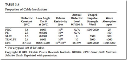
Table 3.4 compares properties of TR-XLPE, EPR, and other insulation mate- rials. Some of the key properties of cable insulation are:
• Dielectric constant (e, also called permittivity) — This determines the cable’s capacitance: the dielectric constant is the ratio of the capac- itance with the insulation material to the capacitance of the same
configuration in free space. Cables with higher capacitance draw more charging current.
• Volume resistivity — Current leakage through the insulation is a function of the insulation’s dc resistivity. Resistivity decreases as temperature increases. Modern insulation has such high resistivity that very little resistive current passes from the conductor through the insulation.
• Dielectric losses — Like a capacitor, a cable has dielectric losses. These losses are due to dipole movements within the polymer or by the movement of charge carriers within the insulation. Dielectric losses contribute to a cable’s resistive leakage current. Dielectric losses increase with frequency and temperature and with operating voltage.
• Dissipation factor (also referred to as the loss angle, loss tangent, tan d, and approximate power factor) — The dissipation factor is the ratio of the resistive current drawn by the cable to the capacitive current drawn (IR/IX). Because the leakage current is normally low, the dissipation factor is approximately the same as the power factor:
Paper-Insulated Lead-Covered (PILC) Cables. Paper-insulated cables have pro- vided reliable underground power delivery for decades. Paper-insulated lead-sheathed cable has been the dominant cable configuration, used mainly in urban areas. PILC cables have kraft-paper tapes wound around the con- ductor that are dried and impregnated with insulating oil. A lead sheath is one of the best moisture blocks: it keeps the oil in and keeps water out. Paper cables are normally rated to 85°C with an emergency rating up to 105°C (EPRI TR-105502, 1995). PILC cables have held up astonishingly well; many 50-year-old cables are still in service with almost new insulation capability. While PILC has had very good reliability, some utilities are concerned about its present day failure, not because of bad design or application, but because the in-service stock is so old. Moisture ingress, loss of oil, and thermal stresses — these are the three main causes of PILC failure (EPRI 1000741, 2000). Water decreases the dielectric strength (especially when the cable is hot) and increases the dielectric losses (further heating the cable). Heat degrades the insulating capability of the paper, and if oil is lost, the paper’s insulating capability declines. PILC use has declined but still not disappeared. Some utilities continue to use it, especially to supply urban networks. Utilities use less PILC because of its high cost, work difficulties, and environmental concerns. Splicing also requires significant skill, and working with the lead sheath requires environmental and health precautions.
Polyethylene (PE). Most modern cables have polymer insulation extruded around the conductor — either polyethylene derivatives or ethylene-propy- lene properties. Polyethylene is a tough, inexpensive polymer with good electrical properties. Most distribution cables made since 1970 are based on some variation of polyethylene. Polyethylene is an ethylene polymer, a long string or chain of connected molecules. In polyethylene, some of the polymer chains align in crystalline regions, which give strength and moisture resis- tance to the material. Other regions have nonaligned polymer chains — these amorphous regions give the material flexibility but are permeable to gas and moisture and are where impurities locate. Polyethylene is a thermoplastic. When heated and softened, the polymer chains break apart (becoming com- pletely amorphous); as it cools, the crystalline regions reform, and the mate- rial returns to its original state. Polyethylene naturally has high density and excellent electrical properties with a volume resistivity of greater than 1014 W-m and an impulse insulation strength of over 2700 V/mil.
High-Molecular Weight Polyethylene (HMWPE). High-molecular weight polyethylene is polyethylene that is stiffer, stronger, and more resistant to chemical attack than standard polyethylene. Insulations with higher molec- ular weights (longer polymer chains) generally have better electrical prop- erties. As with standard polyethylene, HMWPE insulation is a thermoplastic rated to 75°C. Polyethylene softens considerably as temperature increases. Since plastics are stable and seem to last forever, when utilities first installed HMWPE in the late 1960s and early 1970s, utilities and manufacturers expected long life for polyethylene cables. In practice, failure rates increased dramatically after as little as 5 years of service. The electrical insulating strength (the dielectric strength) of HMWPE was degraded by water treeing, an electrochemical degradation driven by the presence of water and voltage. Polyethylene also degrades quickly under partial discharges; once partial discharges start, they can quickly eat away the insulation. Because of high failure rates, HMWPE insulation is off the market now, but utilities still have many miles of this cable in the ground.
Cross-Linked Polyethylene (XLPE). Cross-linking agents are added that form bonds between polymer chains. The cross-linking bonds interconnect the chains and make XLPE semi-crystalline and add stiffness. XLPE is a ther- moset: the material is vulcanized (also called “cured”), irreversibly creating
the cross-linking that sets when the insulation cools. XLPE has about the same insulation strengths as polyethylene, is more rigid, and resists water treeing better than polyethylene. Although not as bad as HMWPE, pre-1980s XLPE has proven susceptible to premature failures because of water treeing. XLPE has higher temperature ratings than HWMPE; cables are rated to 90°C under normal conditions and 130°C for emergency conditions.
Tree-Retardant Cross-Linked Polyethylene (TR-XLPE). This has adders to XLPE that slow the growth of water trees. Tree-retardant versions of XLPE have almost totally displaced XLPE in medium-voltage cables. Various com- pounds when added to XLPE reduce its tendency to grow water trees under voltage. These additives tend to slightly reduce XLPE’s electrical properties, slightly increase dielectric losses, and slightly lower initial insulation strength (but much better insulation strength when aged). While there is no standard industry definition of TR-XLPE, different manufacturers offer XLPE compounds with various adders that reduce tree growth. The oldest and most widely used formulation was developed by Union Carbide (now Dow); their HFDA 4202 tree-retardant XLPE maintains its insulation strength better in accelerated aging tests (EPRI TR-108405-V1, 1997) and in field service (Katz and Walker, 1998) than standard XLPE.
Ethylene-Propylene Rubber (EPR). EPR compounds are polymers made from ethylene and propylene. Manufacturers offer different ethylene-propylene formulations, which collectively are referred to as EPR. EPR compounds are thermoset, normally with a high-temperature steam curing process that sets cross-linking agents. EPR compounds have high concentrations of clay fillers that provide its stiffness. EPR is very flexible and rubbery. When new, EPR only has half of the insulation strength as XLPE, but as it ages, its insulation strength does not decrease nearly as much as that of XLPE. EPR is naturally quite resistant to water trees, and EPR has a proven reliable record in the field. EPR has very good high-temperature performance. Although soft, it deforms less at high temperature than XLPE and maintains its insulation strength well at high temperature (Brown, 1983). Most new EPR cables are rated to 105°C under normal conditions and to 140°C for emergency condi- tions, the MV-105 designation per UL Standard 1072. (Historically, both XLPE and EPR cables were rated to 90°C normal and 130°C emergency.) In addition to its use as cable insulation, most splices and joints are made of EPR com- pounds. EPR has higher dielectric losses than XLPE; depending on the par- ticular formulation, EPR can have two to three times the losses of XLPE to over ten times the losses of XLPE. These losses increase the cost of operation over its lifetime. While not as common or as widely used as XLPE in the utility market, EPR dominates for medium-voltage industrial applications.
TR-XLPE vs. EPR: which to use? Of the largest investor-owned utilities 56% specify TR-XLPE cables, 24% specify EPR, and the remainder specify a mix (Dudas and Cochran, 1999). Trends are similar at rural cooperatives. In a survey of the co-ops with the largest installed base of underground cable, 42% specify TR-XLPE, 34% specify EPR, and the rest specify both (Dudas and Rodgers, 1999). When utilities specify both EPR and TR-XLPE, com-
monly EPR is used for 600-A three-phase circuits, and TR-XLPE is used for 200-A applications like URD. Each cable type has advocates. TR-XLPE is less expensive and has lower losses. EPR’s main feature is its long history of reliability and water-tree resistance. EPR is also softer (easier to handle) and has a higher temperature rating (higher ampacity). Boggs and Xu (2001) show how EPR and TR-XLPE are becoming more similar: EPR compounds are being designed that have fewer losses; tree-retardant additives to XLPE make the cable more tree resistant at the expense of increasing its water absorption and slightly increasing losses.
Cables have a voltage rating based on the line-to-line voltage. Standard voltage ratings are 5, 8, 15, 25, and 35 kV. A single-phase circuit with a nominal voltage of 7.2 kV from line to ground must use a 15-kV cable, not an 8-kV cable (because the line-to-line voltage is 12.47 kV).
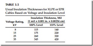
Within each voltage rating, more than one insulation thickness is available. Standards specify three levels of cable insulation based on how the cables are applied. The main factor is grounding and ability to clear line-to-ground faults in order to limit the overvoltage on the unfaulted phases. The standard levels are (AEIC CS5-94, 1994):
• 100 percent level — Allowed where line-to-ground faults can be cleared quickly (at least within one minute); normally appropriate for grounded circuits
• 133 percent level — Where line-to-ground faults can be cleared within one hour; normally can be used on ungrounded circuits
Standards also define a 173% level for situations where faults cannot be cleared within one hour, but manufacturers typically offer the 100 and 133% levels as standard cables; higher insulation needs can be met by a custom order or going to a higher voltage rating. Table 3.5 shows standard insulation thicknesses for XLPE and EPR for each voltage level. In addition to protecting against temporary overvoltages, thicker insulations provide higher insula- tion to lightning and other overvoltages and reduce the chance of failure from water tree growth. For 15-kV class cables, Boucher (1991) reported that 59% of utilities surveyed in North America use 100% insulation (175-mil).
At 25 and 35 kV, the surveyed utilities more universally use 100% insulation (88 and 99%, respectively). Dudas and Cochran (1999) report similar trends in a survey of practices of the 45 largest investor-owned utilities: at 15 kV, 69% of utilities specified 100% insulation; at 25 and 35 kV, over 99% of utilities specified 100% insulation.
Conductors
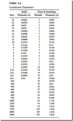
For underground residential distribution (URD) applications, utilities nor- mally use aluminum conductors; Boucher (1991) reported that 80% of utili- ties use aluminum (alloy 1350); the remainder, copper (annealed, soft). Copper is more prevalent in urban duct construction and in industrial appli- cations. Copper has lower resistivity and higher ampacity for a given size; aluminum is less expensive and lighter. Cables are often stranded to increase their flexibility (solid conductor cables are available for less than 2/0). ASTM class B stranding is the standard stranding. Class C has more strands for applications requiring more flexibility. Each layer of strands is wound in an opposite direction. Table 3.6 shows diameters of available conductors.
Neutral or Shield
A cable’s shield, the metallic barrier that surrounds the cable insulation, holds the outside of the cable at (or near) ground potential. It also provides a path for return current and for fault current. The shield also protects the cable from lightning strikes and from current from other fault sources. The metallic shield is also called the sheath.
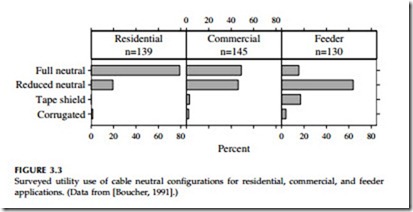
A concentric neutral — a shield capable of carrying unbalanced current — has copper wires wound helically around the insulation shield. The concentric neutral is expected to carry much of the unbalanced load current, with the earth carrying the rest. For single-phase cables, utilities normally use a “full neutral,” meaning that the resistance of the neutral equals that f the phase conductor. Also common is a “one-third neutral,” which has a resistance that is three times that of the phase conductor. In a survey of underground distribution practices, Boucher (1991) reported that full neutrals dominated for residential application, and reduced neutrals are used more for commercial and feeder applications (see Figure 3.3).
Power cables commonly have 5-mil thick copper tape shields. These are wrapped helically around the cable with some overlap. In a tape-shield cable, the shield is not normally expected to carry unbalanced load current. As we
will see, there is an advantage to having a higher resistance shield: the cable ampacity can be higher because there is less circulating current. Shields are also available that are helically wound wires (like a concentric neutral but with smaller wires).
Whether wires or tapes, cable shields and neutrals are copper. Aluminum corrodes too quickly to perform well in this function. Early unjacketed cables
normally had a coating of lead-tin alloy to prevent corrosion. Cable neutrals still corroded. Dudas (1994) reports that in 1993, 84% of utilities specified a bare copper neutral rather than a coated neutral.
The longitudinally corrugated (LC) shield improves performance for fault currents and slows down water entry. The folds of a corrugated copper tape are overlapped over the cable core. The overlapping design allows move- ment and shifting while also slowing down water entry. The design performs better for faults because it is thicker than a tape shield, so it has less resistance, and it tends to distribute current throughout the shield rather than keeping it in a few strands.
Semiconducting Shields
In this application, semiconducting means “somewhat conducting”: the material has some resistance (limited to a volume resistivity of 500 W-m [ANSI/ICEA S-94-649-2000, 2000; ANSI/ICEA S-97-682-2000, 2000]), more than the conductor and less than the insulation. Semiconducting does not refer to nonlinear resistive materials like silicon or metal oxide; the resistance is fixed; it does not vary with voltage. Also called screens or semicons, these semiconducting shields are normally less than 80 mil. The resistive material evens out the electric field at the interface between the phase conductor and the insulation and between the insulation and the neutral or shield. Without the shields, the electric field gradient would concentrate at the closest inter- faces between a wire and the insulation; the increased localized stress could break down the insulation. The shields are made by adding carbon to a normally insulating polymer like EPR or polyethylene or cross-linked poly- ethylene. The conductor shield is normally about 20 to 40 mil thick; the insulation shield is normally about 40 to 80 mil thick. Thicker shields are used on larger diameter cables.
Semiconducting shields are important for smoothing out the electric field, but they also play a critical role in the formation of water trees. The most dangerous water trees are vented trees, those that start at the interface between the insulation and the semiconducting shield. Treeing starts at voids and impurities at this boundary. “Supersmooth” shield formulations have been developed to reduce vented trees (Burns, 1990). These mixtures use finer carbon particles to smooth out the interface. Under accelerated aging tests, cables with supersmooth semiconducting shields outperformed cables with standard semiconducting shields.
Modern manufacturing techniques can extrude the semiconducting conductor shield, the insulation, and the semiconducting insulation shield in one pass. Using this triple extrusion provides cleaner, smoother contact between layers than extruding each layer in a separate pass.
A note on terminology: a shield is the conductive layer surrounding another part of the cable. The conductor shield surrounds the conductor; the insula- tion shield surrounds the insulation. Used generically, shield refers to the metallic shield (the sheath). Commonly, the metallic shield is called the neutral, the shield, or the sheath. Sometimes, the sheath is used to mean the outer part of the cable, whether conducting or not conducting.
Jacket
Almost all new cables are jacketed, and the most common jacket is an encapsulating jacket (it is extruded between and over the neutral wires). The jacket provides some (but not complete) protection against water entry. It also provides mechanical protection for the neutral. Common LLDPE jackets are 50 to 80 mil thick.
Bare cable, used frequently in the 1970s, had a relatively high failure rate (Dedman and Bowles, 1990). Neutral corrosion was often cited as the main reason for the higher failure rate. At sections with a corroded neutral, the ground return current can heat spots missing neutral strands. Dielectric failure, not neutral corrosion, is still the dominant failure mode (Gurniak, 1996). Without the jacket, water enters easily and accelerates water treeing, which leads to premature dielectric failure.
Several materials are used for jackets. Polyvinyl chloride (PVC) was one of the earliest jacketing materials and is still common. The most common jacket material is made from linear low-density polyethylene (LLDPE). PVC has good jacketing properties, but LLDPE is even better in most regards: mechanical properties, temperature limits, and water entry. Moisture passes through PVC jacketing more than ten times faster than it passes through LLDPE. LLDPE starts to melt at 100°C; PVC is usually more limited, depending on composition. Low-density polyethylene resists abrasion bet- ter and also has a lower coefficient of friction, which makes it easier to pull through conduit.
Semiconducting jackets are also available. Semiconducting jackets provide the grounding advantages of unjacketed cable, while also blocking moisture and physically protecting the cable. When direct buried, an exposed neutral provides an excellent grounding conductor. The neutral in contact with the soil helps improve equipment grounding and improves protection against surges. A semiconducting jacket has a resistivity equivalent to most soils (less than 100 W-m), so it transfers current to the ground the same as an unjacketed cable. NRECA (1993) recommends not using a semiconducting jacket for two reasons. First, semiconducting jackets let more water pass through than LLDPE jackets. Second, the semiconducting jacket could con- tribute to corrosion. The carbon in the jacket (which makes the jacket semi- conducting) is galvanic to the neutral and other nearby metals; especially with water in the cable, the carbon accelerates neutral corrosion. Other nearby objects in the ground such as ground rods or pipes can also corrode more rapidly from the carbon in the jacket.
