Introduction
The performance of discrete transient-suppression components available to engineers has greatly improved within the past 10 years. The variety of reasonably priced devices now available makes it possible to exercise tight control over unwanted voltage excursions and allows the complicated electronic equipment being manufactured today to work as intended. Much of the credit for transient-suppression work goes to the computer industry, which has been dealing with this problem for more than 2 decades.
Discrete transient-suppression hardware can be divided into three basic categories:
• Filters
• Crowbar devices
• Voltage-clamping components
Filter Devices
Filters are designed to pass power-line frequency energy and reject unwanted harmonics and noise. The simplest type of ac power-line filter is a capacitor placed across the voltage source. The impedance of the capacitor forms a voltage divider with the impedance of the source, resulting in attenuation of high-frequency transients. This simple approach has definite limitations in transient-suppression capability and can intro- duce unwanted resonances with inductive components in the power-distribution system. The addition of a series resistance will reduce the undesirable resonant effects, but also will reduce the effectiveness of the capacitor in attenuating transient disturbances.
The conducting enclosure of an electronic device is required to be grounded for reasons of safety. How- ever, this conductor often creates a path for noise currents. Any noise current flowing in a ground loop can create noise by electromagnetic coupling or direct connection through stray capacitances. Such noise volt- ages and currents are associated with the potential differences that appear throughout a large interconnected system of grounding conductors. It usually is impossible to eliminate all common-mode noise voltages in a practical ac power-distribution system. It is possible, however, to exert control over where ground loops will occur and the noise current paths that might result.
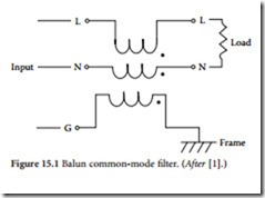
Filters intended for ac power applications are usually low-pass devices that remove high-frequency common-mode electrical noise. Figure 15.1 illustrates a common filter, known as a balun. The balun passes the flow of normal-mode current without significant voltage drop because the power conductors, wound on a common core, are wound in opposition. Load current does not saturate the core. High-frequency noise or impulse signals appearing between the equipment ground conductor and the DP load are attenuated by the device because of the high impedance presented to the noise signals. The ground voltage offset appears across the device, where it will do no harm. Almost identical voltages also appear across the neutral and line conductor coils, thereby offsetting their voltage-to-equipment ground by the same amount as the frame-to- ground offset.
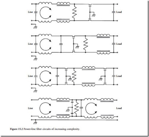
can be regarded as mismatching networks at high frequencies. To operate properly without interaction, filters typically are designed to operate most effectively when the input and output impedances are matched to the respective impedances of the power source and the load. These parameters are not always constant, however. Practical filters often must be designed for compromise conditions. The result may be unwanted ringing or line-voltage distortions at some frequency other than the disturbance frequency, which the filter is intended to correct.
Filters can be composed of lumped, distributed, or dissipative elements; the type used is primarily a function of frequency. Filters, in general, are classified according to the band of frequencies to be transmitted or attenuated. The basic types illustrated in Figure 15.3 are low-pass, high-pass, bandpass, and bandstop (reject).

