Substation Transformers
In a distribution substation, power-class transformers provide the conversion from subtransmission circuits to the distribution primary. Most are connected delta – grounded wye to provide a ground source for the distribution neutral and to isolate the distribution ground system from the sub- transmission system.
Station transformers can range from 5 MVA in smaller rural substations to over 80 MVA at urban stations (base ratings). Stations with two banks, each about 20 MVA, are common. Such a station can serve about six to eight feeders. Power transformers have multiple ratings, depending on cooling methods. The base rating is the self-cooled rating, just due to the natural flow to the surrounding air through radiators. The transformer can supply more load with extra cooling turned on. Normally, fans blow air across the radiators and/or oil circulating pumps. Station transformers are commonly supplied with OA/FA/FOA ratings. The OA is open air, FA is forced air cooling, and FOA is forced air cooling plus oil circulating pumps.
The ANSI ratings were revised in the year 2000 to make them more consistent with IEC designations. This system has a four-letter code that indicates the cooling (IEEE C57.12.00-2000):
• First letter — Internal cooling medium in contact with the windings:
• O mineral oil or synthetic insulating liquid with fire point = 300˚C
• K insulating liquid with fire point > 300˚C
• L insulating liquid with no measurable fire point
• Second letter — Circulation mechanism for internal cooling medium:
• N natural convection flow through cooling equipment and in windings
• F forced circulation through cooling equipment (i.e., coolant pumps); natural convection flow in windings (also called nondi- rected flow)
• D forced circulation through cooling equipment, directed from the cooling equipment into at least the main windings
• Third letter — External cooling medium:
• A air
• W water
• Fourth letter — Circulation mechanism for external cooling medium:
• N natural convection
• F forced circulation: fans (air cooling), pumps (water cooling)
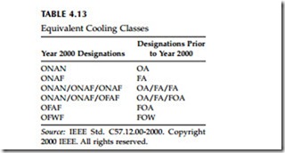
So, OA/FA/FOA is equivalent to ONAN/ONAF/OFAF. Each cooling level typically provides an extra one-third capability: 21/28/35 MVA. Table
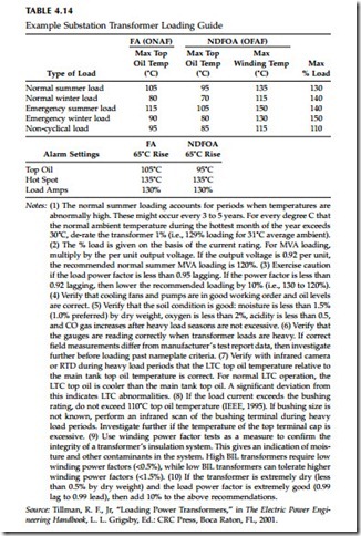
4.13 shows equivalent cooling classes in the old and new naming schemes. Utilities do not overload substation transformers as much as distribution transformers, but they do run them hot at times. As with distribution trans- formers, the tradeoff is loss of life versus the immediate replacement cost of the transformer. Ambient conditions also affect loading. Summer peaks are much worse than winter peaks. IEEE Std. C57.91-1995 provides detailed loading guidelines and also suggests an approximate adjustment of 1% of the maximum nameplate rating for every degree C above or below 30°C. The hottest spot conductor temperature is the critical point where insulation degrades. Above a hot-spot conductor temperature of 110°C, life expectancy decreases exponentially. The life halves for every 8°C increase in operating temperature. Most of the time, the hottest temperatures are nowhere near
this. Tillman (2001) provides the loading guide for station transformers shown in Table 4.14.
The impedance of station transformers is normally about 7 to 10%. This is the impedance on the base rating, the self-cooled rating (OA or ONAN). The impedance is normally higher for voltages on the high-side of the trans- former that are higher (like 230 kV). Transformer impedance can be specified when ordering. Large stations with 50 plus MVA transformers are normally provided with extra impedance to control fault currents, some as high as 30% on the transformer’s base rating.
The positive and zero-sequence impedances are the same for a shell-type transformer, so the bolted fault currents on the secondary of the transformer are the same for a three-phase fault and for a line-to-ground fault (provided that both are fed from an infinite bus). In a three-legged core type trans- former, the zero-sequence impedance is lower than the positive-sequence
impedance (typically Z0
= 0.85Z1), so ground faults can cause higher currents. With a three-legged core transformer design, there is no path for zero- sequence flux. Therefore, zero-sequence current will meet a lower-impedance branch. This makes the core-type transformer act as if it had a delta- connected tertiary winding. This is the magnetizing branch (from line to ground), and this effectively reduces the zero-sequence impedance. In a shell-type transformer, there is a path through the iron for flux to flow, so the excitation impedance to zero sequence is high.
Because most distribution circuits are radial, the substation transformer is a critical component. Power transformers normally have a failure rate between 1 to 2% annually (CEA 485 T 1049, 1996; CIGRE working group 12.05, 1983; IEEE Std. 493-1997). Many distribution stations are originally designed with two transformers, where each is able to serve all of the substation’s feeders if one of the transformers fails. Load growth in some areas has severely reduced the ability of one transformer to supply the whole station. To ensure transformer reliability, use good lightning protection and thermal management. Do not use reduced-BIL designs (BIL is the basic lightning impulse insulation level). Also, reclosing and relaying practices should ensure that excessive through faults do not damage transformers.


