Operation Status Under Balanced LVRT
After the parameters for each converter topology are settled, the operation status with the information of output voltage, load current and delivered power under various LVRT conditions can be derived and simulated. In order to facilitate the investigation and demonstration of the converter operation characteristics under LVRT, three-phase balanced grid faults are first taken into account.
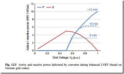
Figure 12.5 summarizes the active/reactive power delivered by the grid side converter under various balanced grid voltage dips of three-phases. Because the injected reactive current under LVRT is defined by German grid codes, the reactive power Q delivered by the converter is only decided by the grid voltage. However, there is still some flexibility to adjust the active current when the grid voltage is above 0.5 p.u. In order to reduce the stress of braking chopper on DC bus and maintain the DC bus voltage, the active power P delivered by the converter under grid voltage above 0.5 p.u. should refer to the generated power by wind turbines. The worst condition is assumed when the generation system is set to provide as much active power as possible, and the pitch control of wind turbine does not have
enough time to activate. The situations of 12 m/s wind speed (10 MW generated power), 10 m/s (6.3 MW generated power), and 8 m/s (3.2 MW generated power) are indicated, respectively, in Fig. 12.5.
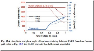
The current amplitude and phase angle (between load current and grid voltage) under three-phase balanced LVRT are shown in Fig. 12.6, in which the situation of different wind speeds at 12, 10, and 8 m/s are indicated respectively. It can be seen that when the grid voltage is below 0.5 p.u., both the current amplitude and phase angle are kept constant because of 100 % rated reactive current injection; however, when the grid voltage is above 0.5 p.u., the current amplitude and phase angle dramatically change with the variation of grid voltage and wind speed.
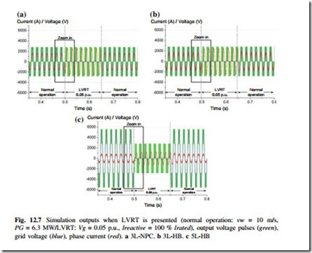
The simulations are carried out based on PLECS Blockset in Simulink, and the simulation parameters are consistent with the ones in Table 12.1. A normal
operation status of each converter is first assumed at wind speed of 10 m/s, which is the typical average annual offshore wind speed defined by IEC I wind class standard. As an extreme example, the converters are subjected to 0.05 p.u. balanced grid voltage dips for 150 ms during the defined normal operation status. Studies of output pulses (green), load current (red), and grid voltage (blue) of each converter topology are presented in Fig. 12.7. It is obvious that, the current amplitude during LVRT with 0.05 p.u. grid voltage increases significantly in all of the three converter topologies compared to the normal operation with 10 m/s wind speed.
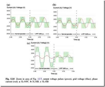
When zooming in the indicated areas of Fig. 12.7, the detailed output waveforms before and after LVRT are shown in Fig. 12.8. Compared to the normal operation with 10 m/s wind speed, the converter outputs when undergoing LVRT with 0.05 p.u. grid voltage have significant changes on the current amplitude, phase angle, and voltage-pulse width. It can be seen that the load current lags the grid voltage by 90 ° because of 100 % reactive current injection, and the output voltage-pulse width is largely reduced because of lower modulation index. It is noted that the output voltage level reduces from five to three in the 5L-HB topology when LVRT operation is presented.
The current distribution in the power switching devices of Fig. 12.8 are shown in Fig. 12.9. It is found that the current load moves from transistor to diodes (both freewheeling and clamped diodes) in the entire three converter topologies during
balanced LVRT, and the increased current amplitude will increase the stress of the power devices compared to the normal operational condition.


