Loss Distribution Under Balanced LVRT
Press-pack IGCT were introduced into the medium voltage converters in 1990s and are already becoming state of the art in high power electric drives (e.g,. for oil and gas applications), but not yet widely adopted in the wind turbine industry also because of cost issues. In this special topic, the press-pack IGCT 5SHY35L4512 (commutated voltage 2.8 kV/maximum current 3.3 kA rms) and diodes 5SDF16L4503 (2.8 kV/2.6 kAr ms) from ABB are chosen as the switching power devices for 3L-NPC and 3L-HB topologies, IGCT 5SHY35L4510 (2.8 kV/2.7 kA rms) and diodes 5SDF10H4503 (2.8 kV/1.8 kA rms) are chosen for the 5L-HB topology. The used loss model is a commonly accepted method for loss evaluation of power semiconductor devices, and the loss simulation is carried out based on PLECS Blockset in Simulink. Losses dissipated in the power devices are considered temperature independent during the simulation.
It is noted that during the LVRT operation, the DC bus of power converter may probably increase because of the short-term mismatch in the input and output active power through the converter. Normally, the increased DC bus voltage should be limited (e.g., maximum 110 % rated) for hundreds of milliseconds by triggering the braking chopper. According to the loss model in [22], the DC bus voltage has important impacts on both the switching loss and the conduction loss in power switching devices. As a result, the increased DC bus voltage should be taken into account in the loss analysis during LVRT. Moreover, the increased DC bus voltage may significantly decrease the lifetime of power switching devices due to the cosmic radiation failure mechanism; however, this issue will not be discussed in this special topic.
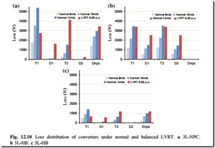
The loss distribution in the power switching devices under normal operation with wind speed of 8, 10, 12 m/s, as well as balanced LVRT condition with 0.05 p.
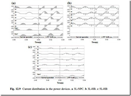
u. grid voltage are compared in Fig. 12.10, in which 10 % higher DC bus voltage or 6.2 kV) are applied for LVRT condition. It can be seen that, the LVRT operation may impose the diodes (D1, D2, Dnpc) and inner switches (T2 in 3L-NPC and 5L-HB) with significantly larger losses than the most stressed normal operation condition (12 m/s wind speed, 10 MW rated output power). The loss simulation results are consistent with the current distributions in Fig. 12.9, in which the diodes and inner switches are heavily loaded because of increased current amplitude and moved phase angle between load current and grid voltage.

