Thermal Analysis of Different Device Solutions
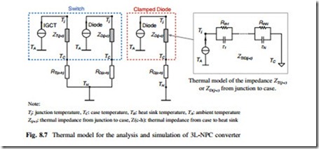
The used thermal models of a single switch and clamping diode are indicated in Fig. 8.7 in which the thermal impedance from junction to case Z(j−c) is modeled as a multi-layer Foster RC network. Each of the thermal parameters can be found from
the manufacturer datasheets, where the thermal resistance Rth will decide the steady-state mean value of junction temperature, and the thermal capacitance (with time constant τ) will decide the dynamic change or fluctuation of the junction temperature.
It is noted that, normally the IGBT manufacturer will only provide thermal parameters inside IGBT modules with Foster RC network, in order to establish the complete thermal models from junction to the ambient, the thermal impedance of ZT/D(j−c) has to be transferred to the equivalent Cauer RC network to facilitate the thermal impedance extension outside IGBT modules. Because the temperature of the heat sink TH is normally much lower and more stable compared to the junction temperature Tj in a properly designed converter system, so the heat sink temperature is considered as a constant value at 60 °C in this special topic. However, the heat sink temperature may strongly depend on the operation site and the design of the heat sink system.
After the parameters for the converter as well as the loss and thermal models for the power switching devices are settled, some important operation modes of the 3L-NPC converter can be simulated. The simulations are carried out based on PLECS blockset in Simulink, and the simulation parameters are consistent with the ones in Tables 8.1 and 8.2, the main focus will be on the grid connected inverter.
Normal Operation
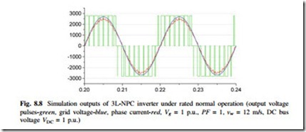
The thermal cycling performance of the 3L-NPC wind power inverter when the wind turbine is running at rated wind speed 12 m/s and rated grid voltage will first be analyzed. Figure 8.8 shows the converter output voltage pulses, phase current, and grid voltage under rated and normal condition of the wind turbines. It can be seen that the load current is in phase with the grid voltage, i.e., power factor PF = 1.
Loss Distribution
The loss calculation method is a commonly accepted method for the loss evaluation of power semiconductor devices. It is noted that the switching loss profile of the chosen switching devices only have the test condition at 125 °C on datasheet, therefore, the loss models in this special topic are considered temperature inde- pendent during the simulation. However, if the device characteristics under other temperatures are provided, the loss model with junction temperature dependence can be established and simulated by iteration in the simulation software.
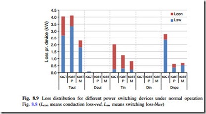
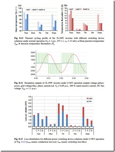
The loss distribution of the 3L-NPC converter with different device solutions under normal rated condition is shown in Fig. 8.9, where only one single device is indicated if parallel power device solutions are applied.
As it can be seen from Fig. 8.9, the major losses for all of the device solutions are consumed by the outer switches Tout, inner switches Tin and the clamping diodes
Dnpc under normal operation of the wind power converter. The IGCT solution shows significantly larger loss in Dnpc due to larger switching loss, on the other hand, the IGBT module solution shows significantly lower overall loss level especially in Tout.
Thermal Performances
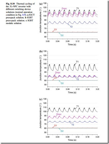
With the thermal model in Fig. 8.7 and loss information in Fig. 8.9, the junction temperature for the switching devices in the given 3L-NPC inverter can be also simulated, as shown in Fig. 8.10, where only one single device is indicated if the parallel power device solutions are applied. It can be seen that the thermal distribution with different device solutions are quite different.
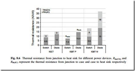
The junction temperature mean value Tjm and temperature fluctuation ΔTj for each of the switching device by different device solutions in Fig. 8.11 are sum- marized in Fig. 8.12. Obviously, the IGCT solution has larger Tjm and ΔTj in almost all of the switching devices, especially the clamping diode Dnpc. For the IGBT press-pack solution, it shows the lowest Tjm level but relatively higher ΔTj level. The IGBT module solution does not achieve the best thermal performance with the lowest power losses because of much larger thermal resistance.
Low-Voltage-Ride-Through Operation
The simulation output of the 3L-NPC inverter undergoing low voltage rid through (LVRT) operation is shown in Fig. 8.13, in which the grid voltage is set to 0.05 p.u. of the rated value as a severe voltage dip, and the converter has to provide 100 % rated reactive current according to the grid codes. It can be seen that the phase current lags 90° to the grid phase voltage, and the inverter achieves 100 % rated reactive current injection (1.75 kA rms) into the power grid.
Loss Distribution
The loss distribution of the 3L-NPC inverter undergoing the given LVRT operation is shown in Fig. 8.14, where different device solutions are indicated and compared. It can be seen that, the loss distribution is quite different from the one undergoing normal operation in Fig. 8.10, Tin has the highest power loss for all of the device solutions. IGCT solution again shows significantly larger loss in Dnpc, while IGBT module solution has the lowest power loss level.
Thermal Performances
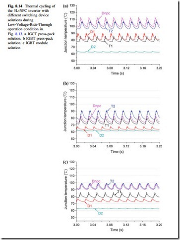
The junction temperature for each of the power switching device in the given 3L-NPC inverter can be also simulated under LVRT operation, as shown in Fig. 8.15, where only one single device is indicated if parallel power device solutions are applied. It can be seen that the thermal distribution with different device solutions are still quite different from each other under LVRT operation of wind turbines.
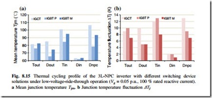
The junction temperature mean value Tjm and temperature fluctuation ΔTj for each of the switching devices by different device solutions in Fig. 8.15 are sum- marized in Fig. 8.16. It can be seen that, again the IGCT solution has larger Tjm and ΔTj in almost all of the switching devices, especially for the clamping diode Dnpc. The IGBT press-pack solution shows the lower Tjm but higher ΔTj compared to the other two device solutions.
Wind Gust Operation
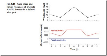
The wind gust operation of wind turbines may impose power switching devices with large thermal cycling amplitude and longer time disturbances compared to the LVRT and normal operation modes. According to the one-year return period wind gust definition by IEC standards, a wind gust condition for a case study is indicated in Fig. 8.17, where the wind speed is set from 10 m/s dropping to 8 m/s and rising to 16 m/s, then the reverse fashion is continued.
Thermal Performances
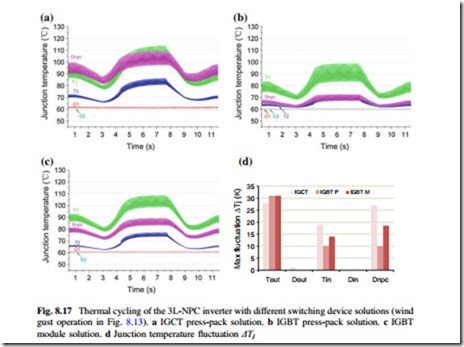
The junction temperature distributions of the target 3L-NPC inverter during the given wind gust operation condition are indicated in Fig. 8.17. It is obvious that, three device solutions show significant differences in the most stressed devices, temperature fluctuation amplitude, and thermal distribution.
The maximum junction temperature fluctuation amplitude with different device solutions are summarized in Fig. 8.17d, it can be seen that the temperature in Tout is
he most fluctuated device in all of the proposed solutions, and IGCT solution shows more temperature fluctuation amplitude in Tin and Dnpc under the given wind gust defined by the IEC standards.
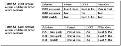
Summary of Thermal Performances Under Different Operation Modes Finally, both the most stressed and the least stressed devices of 3L-NPC inverter with different device solutions are summarized in Tables 8.3 and 8.4 respectively, where the defined three operation modes of wind turbines are included.
It is interesting to see that for all of the power switching device solutions, the outer switches Tout, clamping diodes Dnpc, and inner switch Tin are likely to become the most stressed devices under various operations of wind turbines; while the outer diode Dout and inner diode Din are barely used with all of the device solutions under various operation modes. This information may be used to guide the design and selection of power device for 3L-NPC wind power converter.
