Low-voltage switchgear
Switches, disconnectors, switch disconnectors and fuse combination units
Construction and operation
These switches are categorized by the ability to make and break current to particular duties which are listed for ac applications in Table 7.1. The category depends upon a multiple of the normal operating current and an associated power factor.
In all these devices, the contacts are usually made of silver-plated copper; it is unusual to find the alloy contact tips used in circuit breakers. The contact system, connecting copper work and terminals, is usually in a housing of thermoset plastic or of a thermoplastic with a high temperature capability. The mechanism of the switch may be located in a number of positions, but it is usual to mount it at the side of or below the contact system.
The switching devices may be fitted with auxiliaries which normally take the form of small switches attached to the main device. These auxiliary switches provide means of indication and monitoring of the position of the switch.
There are switching devices that are motor-assisted to open and close the contacts, and some have tripping devices incorporated into the mechanism to open the switch under circuit conditions outside the protective characteristics of the fuse.
Many types of fuse link can be accommodated on a switch fuse or a fuse switch. In the UK, the bolted type is probably the most common, followed by the ‘clip-in’ type. There are many designs available to hold the clip-in fuselink within the switch moulding. In continental Europe the DIN type fuselink is the most common; here the fuse tags are formed as knife blades to fit into spring-tensioned clips.
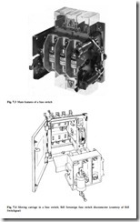
The construction of a fuse switch is illustrated generally in Fig. 7.3. It consists of a moving carriage containing the fuselinks, which is switched into and out of a fixed system containing the contacts and mechanism. The moving carriage is shown in Fig. 7.4; it consists of a plastic and steel framework with copper contacts and terminals onto which are mounted the fuselinks. This is normally a three-pole or four-pole construction. It is usual to be able to extract the moving carriage to facilitate the changing of fuselinks outside the switch. Removal of the carriage also ensures total
isolation of the load from the supply. The moving carriage is moved in and out by a spring-charged mechanism that ensures a quick make and break of the contacts.
In a switch fuse the fuselinks remain static; the simplest form is a knife blade contact in series with a fuselink. In the modern form of switch fuse the fuselinks are mounted on a plastic enclosure which contains the contacts and the mechanism to operate these contacts. The contacts are normally arranged on both load-side and supply-side of the fuselink in order to ensure that the fuse is isolated when the switch is in the off position. The contact system is driven by a spring-assisted mechanism which is usually designed to provide quick make and break operation independent of the speed at which the operator moves the on–off handle.
In its simplest form, the switch is a knife blade contact, but the modern switch would follow the form of the fuse switch without the fuselinks. Many manufacturers use a fuse switch or a switch fuse with solid copper links in place of the fuselinks.
The disconnector also follows the construction of the switch, but it must be capable of providing complete isolation when the contacts are open. This usually requires the provision of adequate clearance and creepage distances between live parts.
The switch-disconnector combines the properties of a switch and a disconnector; this is in most cases what a manufacturer would build for sale.
Standards and testing
Switches, disconnectors, switch disconnectors and fuse combination units are designed to comply with the requirements of IEC 947-3 or EN 60947-3. This requires a combination of type tests and routine tests.
A sequence of type tests is required to prove compliance with the standard. This sequence includes the following key tests:
● the making and breaking switching capacity test, which shows that the device is suitable for extreme overload conditions of resistive, inductive or highly inductive loads. The categories of duty and the current overload ratings have been shown in Table 7.1. The test is carried out by operating the device a number of times at the assigned rating.
● temperature-rise verification. This is carried out at the highest current rating of the device to prove that under full-load conditions in service the device will not damage cables, terminals and insulating materials or put operators at risk through contact with hot accessible parts. The limits of acceptable temperature rise are stipulated in the standard.
● the operational performance test. This is conducted to prove the mechanical and electrical durability of the device. A number of on-load and off-load switching operations are made, depending upon the make/break duty assigned by the manufacturer.
● dielectric verification to prove that the device has completed the sequence with- out damage to its insulation system.
A fuse switch or switch fuse is also proven by a fuse-protected short-circuit withstand (breaking) test. In this test, the fuselinks used have to be of the maximum rating, and with a breaking capacity assigned by the manufacturer. No damage such as welding of the contacts must occur to the switch as a result of this test. A fuse-protected making test is also carried out in which the switch is closed onto the declared rated short-circuit current.
A disconnector has to provide isolation properties and additional type tests are performed to prove these. In particular, a leakage current test is conducted after the main test sequence; maximum levels of acceptable leakage current are specified. In addition, the isolator handle is subjected to a force of three times the normal operation force necessary to switch the device off (within given minimum and maximum limits), the contacts of one phase being artificially locked in the off position and the test force being applied to open the switch. The on–off indicators of the disconnector must not give a false indication during and after this test.
Routine tests to be applied to all switch devices include an operational check in which each device is operated five times to check mechanical integrity. Also a dielectric test is carried out at a voltage which depends upon the rated voltage of the device. For a rated operating voltage of 380/415 V the dielectric test voltage is 2500 V.
Air circuit breakers and moulded case circuit breakers
Construction and operation
Both the air circuit breaker and the moulded case circuit breaker (mccb) comprise the following features:
• a contact system with arc-quenching and current-limiting means
• a mechanism to open and close the contacts
• auxiliaries which provide additional means of protection and indication of the switch positions
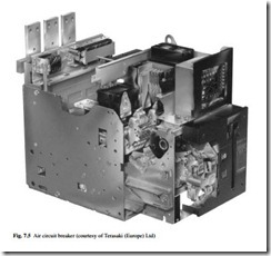
The modern air circuit breaker is generally used as an incoming device on the supply side of a low voltage switchboard, and it represents the first line of protection on the load side of the transformer. An example is shown in Fig. 7.5. In addition to the above features, it also includes:
● a tripping and protection system to open the circuit breaker under fault conditions (if required)
● a means of isolating the device from the busbars
● usually an open construction, or the contact system housed in a plastic moulding
● current ratings from 400 A to 6300 A The mccb may be used as an incoming device, but it is more generally used as an outgoing device on the load side of a switchboard. It is normally mounted into a low-voltage switchboard or a purpose-designed panel board. In addition to the three features listed at the start of this section, it also includes:
● an electronic or thermal/electromagnetic trip sensing system to operate through the tripping mechanism and open the circuit breaker under overload or fault conditions
● all parts housed within a plastic moulded housing made in two halves
● current ratings usually from 10 A to 1600 A
The basis of the main contact system has been explained in section 7.3.1.1. The fixed contacts are usually mounted on a back panel or within a plastic moulding, and
the moving contacts are usually supported on an insulated bar or within an insulated carriage.
In addition to these main contacts, arcing contacts are provided. The arcing contacts generally comprise a silver–tungsten alloy which provides high electrical conductivity with excellent wear against arc erosion and good anti-welding properties. The arc contacts are positioned in such a way that they make first and break last during opening and closing of the contacts. Their purpose is to ensure that any arcing takes place on the arcing contacts before the main contacts touch; the arcing contacts can then break once the main contacts have been forced together. During opening, the sequence is reversed. This action protects the main contacts from damage by arcing.
Extinguishing of the arc is an important feature in all low-voltage switchgear. All air circuit breakers have devices to extinguish the arc as quickly as possible. It is well known that an arc, once formed, will tend to move away from its point of origin; by forming the contact system carefully, the magnetic field generated by the current flow is used to move the arc into an arcing chamber where its extinction is aided.
Within the arcing chamber are a number of metal arc-splitter plates which normally have a slot or ‘V’ shape cut into them in order to encourage the arc to run into the arcing chamber. A typical arrangement is shown in Fig. 7.6. The plates are used to split the arc into a number of smaller arcs, having the effect of lengthening and cooling the arc.
The arc is then extinguished when the voltage drop along it is equal to the voltage across the open contacts.
If the arc can be extinguished very quickly before the full prospective fault current is reached, the maximum current passed through the circuit breaker can be limited. This current limiting is achieved if the arc is extinguished within 10 ms of the start of the fault, before the peak of the sinusoidal current waveform is reached. Many designs have been tried in an attempt to achieve current limiting. Many of these designs are based on forming the current carrying conductors within the circuit breaker in such a way that the electromagnetic forces created by the currents force the arc into the arcing chamber very quickly. A particular development of this is to form ‘blow-out’ coils from the current-carrying conductors.
The opening and closing mechanism of an air circuit breaker generally uses the energy developed in releasing a charged spring. The spring may be charged manually or with the aid of a winding mechanism attached to a motor. The charge is usually held until a release mechanism is activated, and once the spring energy is released to the main mechanism, linkages are moved into an over-toggle mode to close the moving contacts onto the fixed contacts. The force of the main spring is also used to transfer energy into compressing the moving contact springs, and it is these springs which pro- vide the energy to open the contacts when required.
Attached to and interfacing with the main mechanism is the tripping mechanism which is used to open the contacts. The means of tripping an air circuit breaker is a coil, which may be a shunt trip coil, an undervoltage coil or a polarized trip coil. The shunt trip coil is current-operated and consists of a winding on a bobbin with a moving core at its centre. When a current flows, the magnetic flux causes the core to move and this
core operates the trip mechanism. An undervoltage coil is similar in construction, but the moving core is held in place by the magnetic flux against a spring; if the voltage across the winding falls this allows the spring to release the core and operate the trip mechanism. In the polarizing trip coil, the output of the coil is used to nullify the magnetic field from a permanent magnet which is set into the coil; when the coil is energized, the permanent magnetic field is overcome and using the spring energy, a moving core is released to operate the trip mechanism.
The release coil receives its signal from the overcurrent detection device, which is usually an electronic tripping unit. This tripping unit has the capability to detect overloads and short circuits, and it may be able to detect earth fault currents. The overload protection device detects an overload current and relates this to the time for which the current has flowed before initiating a trip signal; the time–current characteristic which is followed here is determined by the manufacturer within the guidelines of the standard. The general principles of time–current protection are explained more fully in Chapter 8, but a typical time–current characteristic is shown for convenience in Fig. 7.7. The short-circuit protection enables a high fault current to be detected and the circuit breaker to be opened in less than 20 ms. The short-circuit protection characteristics
are usually adjustable in multiples of the full-load rated current, and they may incorporate a time interval which would usually be less than a second.
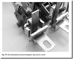
The mccb also incorporates an electronic trip device similar to that described here, but this may not include all of the sophistication of the air circuit breaker system. Some mccbs will include an electromechanical thermal trip and electromagnetic trip in place of the electronic trip unit. These trips are shown in Fig. 7.8. The electromechanical thermal trip consists of a heater and bimetal, the heater being part of the main current-carrying circuit. In overload conditions the heater causes deflection of the bimetal which is time-related depending upon the current flow through the heater. The bimetal deflection results in operation of the trip mechanism and hence a time–current characteristic can be drawn for the circuit breaker. An electromagnetic trip usually comprises a ‘U’-shaped coil around the current-carrying circuit of the mccb, together with a moving pole piece. When a fault current passes, the magnetic flux within the ‘U’-shaped coil pulls in the pole piece and this movement is used to trip the circuit breaker.
Testing and standards
Low-voltage air circuit breakers and mccbs are designed and tested according to the requirements of IEC 947-2, or EN 60947-2.
A series of type tests are carried out to prove compliance with the standard. This series of tests includes the following:
● a short-circuit capability test. This determines the maximum short circuit current the device can withstand, while after the test, retaining the ability to pass full-load current without overheating, and to allow the circuit breaker limited use. This test is carried out in a short-circuit test laboratory able to deliver exactly the current specified in the standard; large generators and transformers are necessary for this work, making it expensive.
● a short-time withstand test. This establishes that the circuit breaker can carry a short-circuit current for a period of time; in many cases this would be 50 kA for 1 s. A circuit breaker with this capability can be used as an incoming device to a distribution system. Based on the principles of co-ordination explained in Chapter 8, this allows other devices within the distribution system to open before the incoming circuit breaker, thereby not necessarily shutting off all of that distribution system.
● an endurance test. This determines the number of open–close operations the circuit breaker can withstand before some failure occurs which means that the device will no longer carry its rated current safely. The tests are carried out with and without current flowing through the contacts.
● opening during overload or fault conditions. This test verifies that the device opens according to the parameters set by the standard and those given by the manufacturer. It determines the time–current characteristic of the circuit breaker, and example of which has been shown in Fig. 7.7.
● a temperature rise test. This is carried out after all the above type tests. The standard specifies a maximum temperature rise permissible at the terminals and it ensures that the device will be safe to use after short circuits have been cleared and after a long period in service.
Miniature circuit breakers
Like the mccb, the miniature circuit breaker (mcb) has a contact system and means of arc quenching, a mechanism and tripping and protection system to open the circuit breaker under fault conditions.
The mcb has advanced considerably in the past 30 years. Early devices were generally of the ‘zero-cutting’ type, and during a short circuit the current had to pass through a zero before the arc was extinguished; this provided a short-circuit breaking capacity of about 3 kA. Most of these early mcbs were housed in a bakelite moulding. The modern mcb is a much smaller and more sophisticated device. All the recent developments associated with moulded case circuit breakers have been incorporated into mcbs to improve their performance, and with breaking capacities of 10 kA to 16 kA now available, mcbs are used in all areas of commerce and industry as a reli- able means of protection.
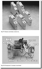
Most mcbs are of single-pole construction for use in single-phase circuits. The complete working system is housed within a plastic moulding, typical external appearance being shown in Fig. 7.9. A section showing the principal parts of the mcb is shown in Fig. 7.10. The contact system comprises a fixed and a moving contact, and attached to each is a contact tip which provides a low-resilience contact junction to resist welding.
Modern mcbs are fitted with arc chutes consisting of metal plates which are held in position by insulating material. The arc chute does not necessarily surround the contact; in some designs arc runners are provided to pull the arc into the arc chute.
The tripping mechanism usually consists of a thermal-magnetic arrangement. The thermal action is provided by a bimetal with, in some cases, a heater. For ratings in the
range 6–63 A the bimetal forms part of the current path, the heat generated within the bimetal itself being sufficient to cause deflection. The deflection is then used to activate the tripping mechanism. The characteristics of the bimetal are chosen to provide particular delays under certain overload or fault currents according to the required time–current characteristic. A high-resistance bimetal is used for low-current devices and a lower resistance bimetal for high-current devices. In very low-current mcbs a heater may be incorporated around the bimetal in order to generate sufficient heat to deflect it.
The magnetic tripping element usually consists of a coil which is wrapped around a tube, there being a spring-loaded slug within the tube. Movement of the slug operates the tripping mechanism to open the mcb. It can also be used to assist in opening the contacts by locating the coil close to the moving contact. When a fault current flows, the high magnetic field generated by the coil overcomes the spring force holding the slug in position; the slug then moves to actuate the tripping mechanism and forces the contacts apart by striking the moving contact arm. For low mcb ratings the coil is formed from thin wire with many turns; for higher ratings the wire is thicker, with fewer turns. The magnetic trip is set by the manufacturer according to the required characteristics. These characteristics are defined in the standard and form ‘types’ which are shown in Table 7.2.
MCBs are designed and tested according to the requirements of IEC 898.
Residual current devices
The residual current device (rcd) is used to detect earth fault currents and to interrupt supply if an earth current flows. The main application is to prevent electrocution but rcds can also be used to protect equipment, especially against fire. The earth fault currents that operate an rcd can range from 5 mA up to many amperes. For typical domestic applications the typical trip current would be 30 mA.
The rcd can be opened and closed manually to switch normal load currents, and it opens automatically when an earth fault current flows which is about 50 per cent or more of the rated tripping current.
The main features of an rcd are shown in Fig. 7.11. The key component is a toroidal transformer, upon which the load current (live) and return current (neutral) conductors are wound in opposite directions. The toroid also carries a detecting winding. If no earth fault current is flowing, then the load and return currents are equal. In this case the mmfs generated by the load and return current windings are equal; there is no result- ant flux in the toroid and the detecting winding does not generate any current. When a fault current flows there is a difference between the load and return currents which generates a resultant flux in the toroid and induces a current in the detecting winding.
The current generated in the detecting winding operates a relay which opens the main contacts of the rcd.
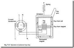
The detecting winding has to produce from a very small output, sufficient power to operate the tripping mechanism. Two alternative methods are used. In the first method, the output signal from the detecting coil is electronically amplified and the second method uses a polarized relay operating on a sensitive mechanical trip mechanism. The operation of a polarized trip relay has already been described for circuit breakers in section 7.3.2.1; it is based on the magnetic output of a small coil nullifying the field from a permanent magnet, causing the release of an armature. The basic operation is illustrated in Fig. 7.12.
The operation of an rcd has here been described for single-phase operation, but it may also be applied in a three-phase application where typically it might be used in a light industrial system for protection against fire. There are two arrangements of a three-phase rcd. Either the three phases are wound around a current transformer, or the three phases and the neutral are wound onto a balancing transformer.
The rcd has only limited breaking capacity and it is not a replacement for overcur- rent protection devices such as the mcb. The residual current breaker with overcurrent (rcbo) is now available; this is an rcd with an overcurrent tripping mechanism and enhanced contacts to cope with interruption of fault conditions.
RCDs are designed and tested according to the requirements of IEC 1008 and IEC 1009.
Standards
The leading international standards adopted by for low-voltage switchgear are shown in Table 7.3.

