Starter circuits
Before assuming that the motor is at fault, check the battery and cables. The temperature-corrected hydrometer reading should be at least 1.240, and no cell should vary from the average of the others by more than 0.05 point. See that the battery terminal connections are tight and free of corrosion.
Excessive or chronic starter failure might point to a problem that is outside the starter itself. It could be caused by an engine that is out of tune and that consequently requires long cranking intervals.
Starter circuit tests
There are several methods that you can use to check the starting-circuit resistance. One method is to open all the connections, scrape bright, and retighten. Another method requires a low-reading ohmmeter of the type sold by Sun Electric and other suppliers for the automotive trades. But most mechanics prefer to test by voltage drop.
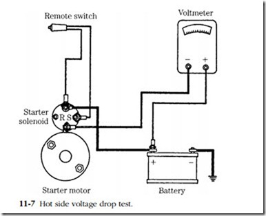
Connect a voltmeter as shown in Fig. 11-7. The meter shunts the positive, or hot battery post and the starter motor. With the meter set on a scale above battery volt- age, crank. Full battery voltage means an open in the circuit.
If the starter functions at all, the reading will be only a fraction of this. Expand the scale accordingly. A perfect circuit will give a zero voltage drop because all cur- rent goes to the battery. In practice some small reading will be obtained. The exact figure depends on the current draw of the starter and varies between engine and starter motor types. As a general rule, subject to modification by experience, a 0.5V drop is normal. Much more than this means: (1) resistance in the cable, (2) resistance in the connections (you can localize this by repeating the test at each connection point), or (3) resistance in the solenoid.
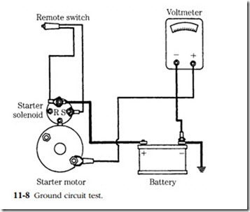
Figure 11-8 shows the connections for the ground-side check. A poor ground, and consequent high voltage on the meter, can occur at the terminals, the cable, or between the starter motor and engine block. If the latter is the case, remove the motor and clean any grease or paint from the mounting flange.
Starter motors
Starter motors are series-wound; i.e., they are wound so that current enters the field coils and goes to the armature through the insulated brushes. Because a series- wound motor is characterized by high no-load rpm, some manufacturers employ limiting coils in shunt with the fields. The effect is to govern the free-running rpm and prolong starter life should the starter be energized without engaging the flywheel.
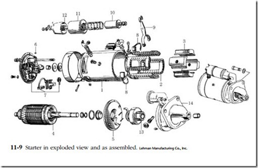
The exploded view in Fig. 11-9 illustrates the major components of a typical starter motor. The frame (No. 1) has several functions. It locates the armature and fields, absorbs torque reaction, and forms part of the magnetic circuit.
The field coils (No. 2) are mounted on the pole shoes (No. 3) and generate a magnetic field, which reacts with the field generated in the armature to produce torque. The pole pieces are secured to the frame by screws.
The armature (No. 4) consists of a steel form and a series of windings, which terminate at the commutator bars. The shaft is integral with it and splined to accept the starter clutch.
The end plates (5 and 6) locate the armature by means of bronze bushings. The commutator end plate doubles as a mounting fixture for the brushes, while the power takeoff side segregates the starter motor from the clutch.
The insulated (hot) brushes (No. 7) provide a current path from the field coils through the commutator and armature windings to the grounded brushes (No. 8).
Engagement of this particular starter is done by means of a yoke (No. 9), which is pivoted by the solenoid plunger (No. 10) in response to current flowing through the solenoid windings (No. 11). Movement of the plunger also trips a relay (No. 12) and energizes the motor. The pinion gear (No. 13) meshes with the ring gear on the rim of the flywheel. The pinion gear is integral with an overrunning clutch.
The starter drive housing supports the power takeoff end of the shaft and pro- vides an accurately machined surface for mounting the starter motor to the ending block or bellhousing.
Brushes
Before any serious work can be done, the starter must be removed from the engine, degreased, and placed on a clean bench. Disconnect one or both cables at the battery to prevent sparking; disconnect the cable to the solenoid and the other leads that might be present (noting their position for assembly later); and remove the starter from the flywheel housing. Starters are mounted with a pair of cap screws or studs.
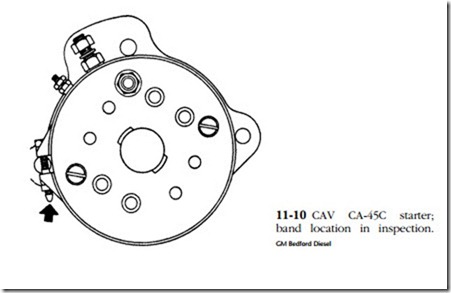
Remove the brush cover, observing the position of the screw or snap, because wrong assembly can short the main cable or solenoid wire (Fig. 11-10). Hitachi starters do not have an inspection band as such. The end plate must be removed for access to the brushes and commutator.
Brushes are sacrificial items and should be replaced when worn to half their original length. The rate of wear should be calculated so that the wear limit will not be reached between inspection periods. Clean the brush holders and commutator with a preparation intended for use on electrical machinery. If old brushes are used,
lightly file the flanks at the contact points with the holders to help prevent sticking. New brushes are contoured to match the commutator, but should be fitted by hand. Wrap a length of sandpaper around the commutator—do not use emery cloth—and turn in the normal direction of rotation. Remove the paper and blow out the dust.
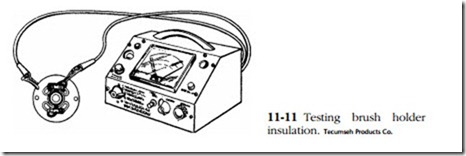
Try to move the holders by hand. Most are riveted to the end plate and can become loose, upsetting the brush-commutator relationship. With an ohmmeter, test the insulation on the hot-side brush holders (Fig. 11-11). There should be no conti- nuity between the insulated brush holders and the end plate. Brush spring tension is an important and often overlooked factor in starter performance. To measure it, you will need an accurate gauge such as one supplied by Sun Electric. Specifications vary between makes and models, but the spring tension measured at the free (brush) end of the spring should be at least 11/2 lb. Some specifications call for 4 lb.
The commutator bars should be examined for arcing, scores, and obvious eccen- tricity. Some discoloration is normal. If more serious faults are not apparent, buff the bars with a strip of 000 sandpaper.
Armature
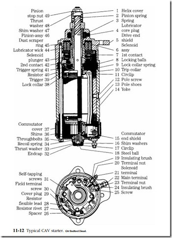
Further disassembly requires that the armature shaft be withdrawn from the clutch mechanism. Some starters employ a snap ring at the power takeoff end of the shaft to define the outer limit of pinion movement. Others use a stop nut (Fig. 11-12, No. 49). The majority of armatures can be withdrawn with the pinion and overrun- ning clutch in place. The disengagement point is at the yoke (Fig. 11-9, No. 9) and sleeve on the clutch body. Remove the screws holding the solenoid housing to the frame and withdraw the yoke pivot pin. The pin might have a threaded fastener with an eccentric journal, as in the case of Ford designs. The eccentric allows for wear compensation. Or it might be a simple cylinder, secured by a flanged head on one side and a cotter pin or snap ring on the other. When the pin is removed there will be enough slack in the mechanism to disengage the yoke from the clutch sleeve, and the armature can be withdrawn. Observe the position of shims—usually located between the commutator and end plate—and, on CAV starters, the spring-loaded ball. This mechanism is shown in Fig. 11-12 as 18 and 34. It allows a degree of end float so that the armature can recoil if the pinion and flywheel ring gear do not mesh on initial contact.
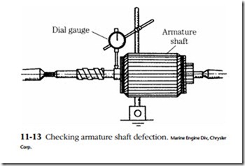
The armature should be placed in a jig and checked for trueness because a bent armature will cause erratic operation and might, in the course of long use, destroy the flywheel ring gear. Figure 11-13 illustrates an armature chucked between lathe
centers. The allowable deflection at the center bearing is 0.002 in., or 0.004 in. on the gauge. With the proper fixtures and skill with an arbor press, an armature shaft can be straightened, although it will not be as strong as it was originally and will be prone to bend again. The wiser course is to purchase a new armature.
Make the same check on the commutator. Allowable out-of-roundness is 0.012– in., or less, depending on the rate of wear and the intervals between inspection periods. Commutators that have lost their trueness or have become pitted should be
turned on a lathe. The cutting tool must be racked more for copper than for steel. Do not allow the copper to smear into the slots between the segments. Chamfer the end of the commutator slightly. Small imperfections can be removed by chucking the commutator in a drill press and turning against a single-cut file.
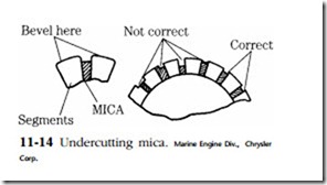
It is necessary that the insulation (called, somewhat anachronistically, mica) be buried below the segment edges; otherwise, the brushes will come into contact with the insulation as the copper segments wear. Undercutting should be limited to 0.015 in. or so. Tools are available for this purpose, but an acceptable job can be done with a hacksaw blade (flattened to fit the groove) and a triangular file for the final bevel cut (Fig. 11-14).
Inspect the armature for evidence of overheating. Extended cranking periods, dragging bearings, chronically low battery charge, or an under-capacity starter will cause the solder to melt at the commutator-armature connections. Solder will be splattered over the inside of the frame. Repairs might be possible because these con- nections are accessible. Continued overheating will cause the insulation to flake and powder. Discoloration is normal, but the insulation should remain resilient.
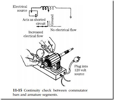
Armature insulation separates the nonferrous parts (notably the commutator seg- ments) from the ferrous parts (the laminated iron segments extending to the outer diameter of the armature and shaft). Make three tests with the aid of a 120V conti- nuity lamp or a megger (meter for very high resistances). An ordinary ohmmeter is useless to measure the high resistances involved. In no case should the lamp light up or resistance be less than 1 Mfl.
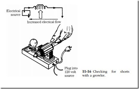
It is possible for the armature windings to short, thus robbing starter torque. Place the armature on a growler and rotate it slowly while holding a hacksaw blade over it as shown in Fig. 11-16. The blade will be strongly attracted to the armature segments because of the magnetic field introduced in the windings by the growler.
Checking for shorts with a growler.
But if the blade does a Mexican hat dance over a segment, you can be sure that the associated winding is shorted.
Field coils
After armatures, the next most likely source of trouble is the field coils. Meld hookups vary. The majority are connected in a simple series circuit, although you will encounter starters with split fields, each pair feeding off its own insulated brush. Field resistance values are not as a rule supplied in shop manuals, although a per- sistent mechanic can obtain this and other valuable test data by contacting the starter manufacturer. Be sure to include the starter model and serial number.
In the absence of a resistance test, which would detect intracoil shorts, the only tests possible are to check field continuity (an ordinary ohmmeter will do) and to check for shorts between the windings and frame. Connect a lamp or megger to the fields and touch the other probe to the frame, as illustrated in Fig. 11-17. Individual fields can be isolated by snipping their leads.
The fields are supported by the pole shoes, which in turn, are secured to the frame by screws. The screws more often than not will be found to have rusted to the frame. A bit of persuasion will be needed, in the form of penetrating oil and elbow grease. Support the frame on a bench fixture and, with a heavy hammer, strike the screwdriver exactly as if you were driving a spike. If this does not work, remove the screw with a cape chisel. However, you might (depending on the starter make and your supply of junk parts) have difficulty in matching the screw thread and head fillet.
Coat the screw heads with Loctite before installation and torque securely. Be sure that the pole shoe and coil clears the armature and that the leads are tucked out of the way.
Bearings
The great majority of starters employ sintered bronze bushings. In time these bushings wear and must be replaced to ensure proper teeth mesh at the flywheel and prevent armature drag. In extreme cases the bushings can wear down to their
bosses so that the shaft rides on the aluminum or steel end plates. The old bushings are pressed out and new ones pressed in. Tools are available to make this job easier, particularly at the blind boss on the commutator end plate.
Without these tools, the bushing can be removed by carefully ridging and col- lapsing it inward, or by means of hydraulic pressure. Obtain a rod that matches shaft diameter. Pack the bushing with grease and hammer the rod into the boss. Because the grease cannot easily escape between the rod and bushing, it will lift the bushing up and out. Because of the blind boss, new bushings are not reamed.
Final tests
The tests described thus far have been static tests. If a starter fails a static test, it will not perform properly, but passing does not guarantee the starter is faultless. The only sure way to test a starter—or, for that matter, any electrical machine—is to mea- sure its performance under known conditions, and against the manufacturer’s spec- ifications or a known-good motor.
No-load performance is checked by mounting the starter in a vise and monitor- ing voltage, current, and rpm. Figure 11-18 shows the layout. The voltage is the ref- erence for the test and is held to 12V. Current drain and rpm are of course variable, depending on the resistance of the windings, their configuration, and whether or not speed-limiting coils are provided. You can expect speeds of 4000–7000 rpm and draws of 60–100A. In this test we are looking for low rpm and excessive current consumption.
The locked-rotor and stall test requires a scale to accept the pinion gear (Fig. 11-19). It must be made quickly, before the insulation melts. Mount the motor securely and lock the pinion. Typically the voltage will drop to half the normal value. Draw might approach or, with the larger starters, exceed 100A.
