In this chapter, several promising converter topologies for the next generation wind power converter are first presented and discussed in respect to their advantages/drawbacks. Later, three potential power semiconductor devices for wind power application are highlighted and basically evaluated.
Promising Converter Topologies
In the past, there has not been much diversity for the converter topology used in wind power applications. Pulse-width-modulation voltage source converters with Two-Level voltage output (2L-PWM-VSC) or simpler circuits were widely used in the low voltage level and they are capable to satisfy most of the requirements. Nevertheless, because of the significantly increased demand for the power capacity, cost-effectiveness, reliability, and controllability, the performance of single 2L-PWM-VSC converter seems to be not enough for the future wind turbine sys- tem. Consequently, a number of more-powerful and advanced power converter solutions for the next generation wind turbines are proposed. In this section, some of the promising configurations either in the academics or in the industry are going to be reviewed and discussed.
2.1.1 Traditional Two-Level Converters
2L-PWM-VSC is the most frequently used topology so far in wind turbine systems. The knowledge available in this converter is extensive and well established. In the wind turbine system, the 2L-PWM-VSC can be used in different configurations which are introduced as follows:
A. Two-Level UNI-Directional Voltage Source Power Converter (2L-UNI)
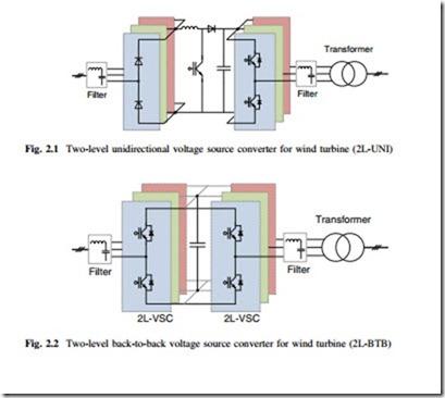
It is becoming popular to use permanent magnet synchronous generator (PMSG) in the WTS. Because there is no reactive power required in such generators and active power flows uni-directionally from the generator to the power grid. Only a simple diode rectifier can be applied on the generator side to achieve cost-efficient solution, as shown in Fig. 2.1. However, the diode rectifier even with multiphase or 12-pulses introduces low frequency pulsations which can trigger the shaft reso- nance in a worst case [1, 2].
B. Two-Level Back-To-Back Voltage Source Power Converter (2L-BTB)
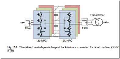
It is very popular to configure two 2L-PWM-VSCs as a back-to-back structure (2L-BTB) in the wind power system, as shown in Fig. 2.2. A technical advantage of the 2L-BTB solution is the full power controllability (4 quadrant operation), with relatively simpler structure and fewer components. The 2L-BTB is the state-of-the-art solution for DFIG-based wind turbine concept [2, 3]. Several manufacturers also use this topology for the wind turbine concept, with full-scale converter and squirrel-cage induction generator.
However, the 2L-PWM-VSC topology may suffer from larger switching losses and lower efficiency when the power conversion is pushed to megawatts (MW) level, and the available power semiconductor devices may need to be con- nected in parallel or in series, to obtain enough current and voltage ratings. Another problem of the 2L-PWM-VSC is the two-level voltage outputs, which introduce large dv/dt stresses to the generator and transformer windings, requiring bulky output filters to limit the voltage gradient and reduce the harmonics level, especially
in the case of long cable connections. Consequently, it is becoming more difficult for the 2L-BTB solution to achieve acceptable performance in the WTS.
2.1.2 Multilevel Converters
With the abilities of more voltage levels and larger power handling capacities, multilevel converters are becoming promising in the future wind turbine system [4]. Generally, the multilevel topologies can be classified into three types [5, 6]: neutral-point diode clamped, flying capacitor clamped, and cascaded converter cells. In order to realize cost-effective design, it is ideal for multilevel converters to be used in the environment with higher power and higher voltage conversion [7], which are preferred features for the next generation wind power converters.
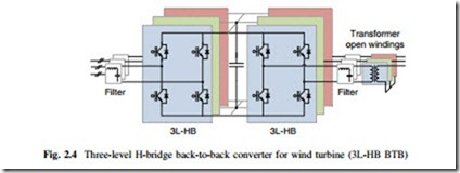
A. Three-Level Neutral Point Diode Clamped Back-to-Back Topology (3L-NPC BTB) Three-level neutral point diode clamped converter is one of the most commercialized multilevel topologies on the market. Similar to the 2L-BTB, it is usually configured as a back-to-back structure in the wind turbine system, as shown in Fig. 2.3, which is called 3L-NPC BTB for convenience.
3L-NPC BTB can achieve one more voltage level output and less dv/dt stress
compared to the 2L-BTB, thereby, the filter size can be smaller under the same power and voltage. The potential fluctuation of the mid-point in the DC-bus, used to be a drawback of the 3L-NPC BTB. This problem has been extensively researched and is considered improved, by the controlling of redundant switching states or by introducing extra circuits [8]. However, it is found that the loss distribution is unequal among the power devices in a switching arm [9, 10], and this problem might lead to de-rated power capacity when it is practically used.
B. Three-Level H-Bridge Back-to-Back Topology (3L-HB BTB)
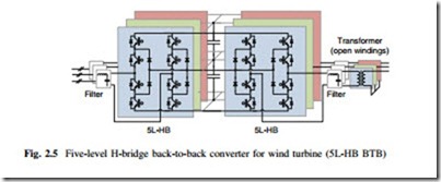
The 3L-HB BTB solution is composed of two 3-phase H-bridge converters con- figured in a back-to-back structure, as shown in Fig. 2.4. It achieves the similar output performance like the 3L-NPC BTB, but the unequal loss distribution and clamping diodes can be avoided. Thereby, more efficient and equal loading of the power switching devices as well as higher designed capacity can be obtained [11]. Moreover, as only half of the DC bus voltage is needed compared to the 3L-NPC BTB, there are less series connection of capacitors and no mid-point in the DC bus.
However, the 3L-HB BTB solution needs an open winding structure both in the generator and transformer in order to achieve isolation among each phase. This feature has both advantages and disadvantages: On one hand, a potential fault tolerant ability is obtained if one or even two phases of the generator are out of operation. On the other hand, extra cost, weight, loss, and inductance/capacitance in the cables can be the major drawbacks, especially in the wind power application.
C. Five-Level H-Bridge Back-to-Back Topology (5L-HB BTB)
The 5L-HB BTB converter is composed of two 3-phase H-bridge converters making use of 3L-NPC switching arms, as shown in Fig. 2.5. It is an extension of 3L-HB BTB solution, and shares the same requirements for the open-winding generator and transformer. 5L-HB BTB can achieve five-voltage-level output, and doubled voltage amplitude compared to the 3L-HB BTB solution with the same
power devices. These features enable smaller output filter and less current rating in the components as well as in the cables [12]. However, the 5L-HB BTB converter introduces more switching devices, unequal loss distribution, and larger DC link capacitors.
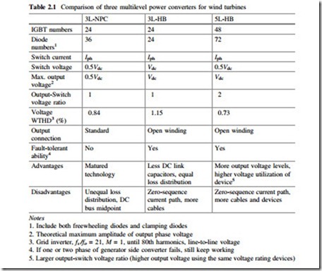
The comparisons between the three multilevel topologies used in the wind turbine system are shown in Table 2.1, in which the number of power semicon- ductor devices, the output performance, fault tolerant ability, as well as major advantages and disadvantages are focused.
2.1.3 Multi-cell Converters
Besides the solution of multilevel converters, some configurations with multi-cell converters, i.e., parallel/series connection of converter cells, are widely adopted by the industry in order to handle the fast growing power of wind turbines.
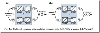
Figure 2.6a shows a multi-cell solution adopted by Gamesa in their 4.5 MW wind turbines [13], which have several 2L-VSCs paralleled, both on the generator side and on the grid side. Siemens also introduce the similar configuration in their best-selling multi-MW wind turbines, as indicated in Fig. 2.6b [14]. The standard and proven low voltage converter cells as well as redundant and modular charac- teristics are the main advantages. This converter configuration is the state-of-the-art industrial solution for the wind turbines higher than 3 MW.
B. Cascaded H-Bridge Converter with Medium-Frequency-Transformers (CHB- MFT)
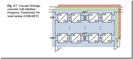
This configuration shares the similar idea with the next generation traction converters [15, 16], and is also proposed in the European UNIFLEX-PM Project [17], as shown in Fig. 2.7. It is based on a structure of back-to-back Cascaded H-bridge converters, with galvanic insulated DC/DC converters as interface. The DC/DC converters have medium frequency transformer (MFT) operating at several kHz to dozens of kHz, thereby the transformer size can be significantly reduced. Moreover, because of the cascaded structure, it can be directly connected to the distribution networks (10−20 kV), with high output quality, redundancy, and filter-less design. This solution would become more attractive if it can be placed in the nacelle of
wind turbines because the bulky low-frequency transformer can be replaced by the more compact and flexibly-configured power semiconductor devices.
C. Modular Multilevel Converter (MMC)
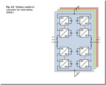
This configuration shares the similar idea with some of the emerging converters used for High Voltage Direct Current (HVDC) Transmission [18, 19], as shown in Fig. 2.8. It is also based on a back-to-back structure with cascaded converter cells of 2L-VSC. One advantage of this configuration is the easily scalable voltage/power capability; therefore, it can achieve high power conversion at dozens of kV with good modularity and redundancy. The output filter can also be eliminated because of significantly increased voltage levels. However, the useable voltage rating in the wind turbine system may be greatly limited by the insulation materials of the generator. Moreover, the low fundamental frequency of the generator outputs (which is the normal case for MW synchronous generator) may introduce large DC voltage fluctuation in the converter cells of generator side, and thereby results in bulky capacitors in the converter system, being un-preferable for the compact design.
It can be seen that, generally the multi-cell converters have modular and redundant features which can contribute to higher fault-tolerant performance. But, on the other hand, all the three configurations have significantly increased com- ponents count, which could compromise the system reliability and increase the cost.
The overall merits and defects of these multi-cell converters used in the wind power application still need to be further evaluated.
More potential power electronic-topologies and technologies used in the wind power application can be found in [20].
