Basic Principles of the Transformer
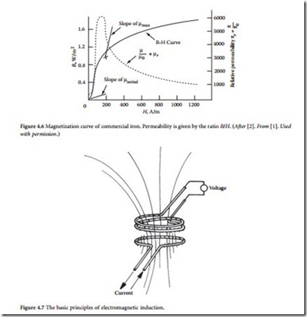
In 1831, English physicist Michael Faraday demonstrated the phenomenon of electromagnetic induction. The concept is best understood in terms of lines of force, a convention Faraday introduced to describe the direction and strength of a magnetic field. The lines of force for the field generated by a current in a loop of wire are shown in Figure 4.7. When a second, independent loop of wire is immersed in a changing magnetic field, a voltage will be induced in the loop. The voltage will be proportional to the time rate of change of the number of force lines enclosed by the loop. If the loop has two turns, such induction occurs in each turn, and twice the voltage results. If the loop has three turns, three times the voltage results, and so on. The concurrent phenomena of mutual induction between the coils and self-induction in each coil form the basis of transformer action.
For a power transformer to do its job effectively, the coils must be coupled tightly and must have high self-induction. That is, almost all the lines of force enclosed by the primary also must be enclosed by the secondary, and the number of force lines produced by a given rate of change of current must be high. Both conditions can be met by wrapping the primary and secondary coils around an iron core, as Faraday did in his early experiments. Iron increases the number of
lines of force generated in the transformer by a factor of about 10,000. This property of iron is referred to as permeability. The iron core also contains the lines so that the primary and secondary coils can be separated spatially and still closely coupled magnetically.
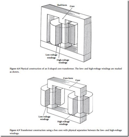
With the principles of the transformer firmly established, American industrialist George Westing- house and his associates made several key refinements that made practical transformers possible. The iron core was constructed of thin sheets of iron cut in the shape of the letter E. Coils of insulated copper wire were wound and placed over the center element of the core. Straight pieces of iron were laid across the ends of the arms to complete the magnetic circuit. This construction still is common today. Figure 4.8 shows a common E-type transformer. Note how the low-voltage and high-voltage windings are stacked on top of each other. An alternative configuration, in which the low-voltage and high-voltage windings are located on separate arms of a core box, is shown in Figure 4.9.
In an ideal transformer, all lines of force pass through all the turns in both coils. Because a changing magnetic field produces the same voltage in each turn of the coil, the total voltage induced in a coil is
proportional to the total number of turns. If no energy is lost in the transformer, the power available in the secondary is equal to the power fed into the primary. In other words, the product of current and volt- age in the primary is equal to the product of current and voltage in the secondary. Thus, the two currents are inversely proportional to the two voltages and therefore, inversely proportional to the turns ratio between the coils. This expression of power and current in a transformer is true only for an ideal trans- former. Practical limitations prevent the perfect transformer from being constructed.
The key properties of importance in transformer core design include:
• Permeability
• Saturation
• Resistivity
• Hysteresis loss
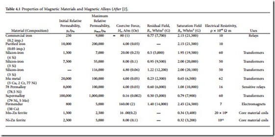
Permeability, as discussed previously, refers to the number of lines of force a material produces in response to a given magnetizing influence. Saturation identifies the point at which the ability of the core to carry a magnetic force reaches a limiting plateau. These two properties define the power-handling capability of the core element. Electrical resistivity is desirable in the core because it minimizes energy losses resulting from eddy currents. In contrast, hysteresis undermines the efficiency of a transformer. Because of the interactions among groups of magnetized atoms, losses are incurred as the frequency of the changing magnetic field is increased. Throughout the history of transformer development, the goal of the design engineer has been to increase permeability, saturation, and resistivity, while decreasing hyster- esis losses. A variety of core materials, including silicon iron in various forms, have been used.
Transformer efficiency is defined as
![]() Losses in a transformer are the result of copper losses in the windings and core losses. The copper losses vary with the square of the current; the core losses vary with the input voltage magnitude and frequency. Because neither of these quantities depend on the power being consumed by the load, power transformers are rated by the voltamperes (VA) that flow through them.
Losses in a transformer are the result of copper losses in the windings and core losses. The copper losses vary with the square of the current; the core losses vary with the input voltage magnitude and frequency. Because neither of these quantities depend on the power being consumed by the load, power transformers are rated by the voltamperes (VA) that flow through them.
The regulation specification of a power transformer is a measure of the transformer’s ability to maintain a constant output voltage under varying loads. The primary voltage is held constant at the value required to produce the rated voltage on the secondary at full load:
Also bearing on transformer performance are electrical insulation and the cooling system used. These two elements are intimately related because the amount of heat that the core and conductors gen- erate determines the longevity of the insulation; the insulation itself — whether solid, liquid, or gas — serves to carry off some portion of the heat produced. Temperatures inside a commercial transformer may reach 100°C, the boiling point of water. Under such conditions, deterioration of insulating materials can limit the useful lifetime of the device. Although oils are inexpensive and effective as insulators and coolants, some oils are flammable, making them unacceptable for units placed inside buildings. Chlori- nated hydrocarbon liquids (PCBs) were used extensively from the 1930s to the late 1970s, but evidence of long-term toxic effects prompted a ban on their use. Some transformers rely on air- or nitrogen-gas- based insulators. Such devices can be installed indoors. The breakdown strength of gas sometimes is enhanced through the addition of small quantities of fluorocarbons. Other dry transformers depend on cast-resin insulation made of polymerizing liquids that harden into high-integrity solids. Progress in heat removal is largely responsible for reducing the overall size of the transformer assembly.
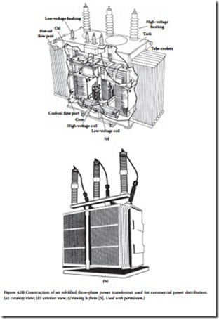
Modern high-power commercial transformers may operate at voltages of 750 kV or more and can handle more than 1000 kVA. The expected lifetime of a commercial power transformer ranges from 24 to 40 years. A typical three-phase oil-cooled transformer is shown in Figure 4.10.
Counter-Electromotive Force
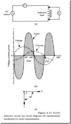
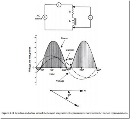
All transformers, generators, and motors exhibit the property of inductance. This property is the result of a counter-emf that is produced when a magnetic field is developed around a coil of wire. Inductance presents an opposition to the change in current flow in a circuit. This opposition is evident in the dia- gram shown in Figure 4.11. In a purely inductive circuit (containing no resistance), the voltage will lead the current by 90˚. How- ever, because all practical circuits have resis- tance, the offset will vary from one circuit to the next. Figure 4.12 illustrates a circuit in which voltage leads current by 30°. The angular separation between voltage and cur- rent is referred to as the phase angle. The phase angle increases as the inductance of the circuit increases. Any inductive circuit exhibits the property of inductance, including electrical power-transmission and distribution lines. The henry is the unit of measurement for inductance. A circuit has a 1 H inductance if a current changing at a rate of 1 A/s produces an induced counter- emf of 1 V.
In an inductive circuit with ac applied, an opposition to current flow is created by the inductance. This opposition is known as inductive reactance (Xl). The inductive reac- tance of a given ac circuit is determined by the inductance of the circuit and the rate of current change. Inductive reactance can be
Full Load Percent Impedance
The full load percent impedance (FLPI) of a transformer is an important parameter in power-supply sys- tem design. FLPI is determined by the construction of the core and physical spacing between the primary and secondary windings. Typical FLPI values range from 1 to 5%. FLPI is a measure of the ability of a transformer to maintain its rated voltage with a varying load. The lower the FLPI, the better the regula- tion. FLPI also determines the maximum fault current that the transformer can deliver. For example, if a 5% FLPI transformer supplying 5 A nominal at the secondary is short-circuited, the device can,
theoretically, supply l00 A at full voltage. A similar transformer with a 10% FLPI can supply only 50 A when short-circuited. Typical short-circuit currents for a selection of small three-phase transformers are listed in Table 4.2.
Design Considerations
As touched upon previously, permeability μ describes the ease with which magnetic flux can be produced in a given material. More flux will be produced in a material with a high permeability than in one with a low permeability, given the same amount of current and the same number of turns in the coil. The ratio of a material’s permeability to the permeability of free space, called relative permeability, is often used [6]. The actual permeability, which has units of webers per ampere-turn-meter, is found by multiplying the permeability of free space by the relative permeability.
The overall ability of a core to carry flux also depends on its size and shape, and its cross-sectional area. This is described by permeance. The basic relationship of permeance to permeability in a core is defined by
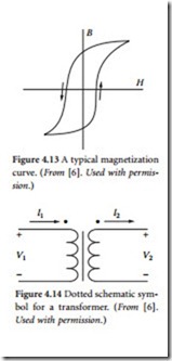
rise in voltage from the unmarked to the marked terminal on each coil. Under this convention, current into the dot on the primary side is labeled as having positive polarity, and current out of the dotted terminal on the other side is assigned positive polarity. This means that the power flow must be into the transformer on one side and out of the transformer on the other side.
The Ideal Transformer
Although no transformer is ideal in its characteristics, transformers approach their ideal characteristics in the operating range for which they were designed. The ideal transformer has no coil resistance and no core losses, so that it has no power loss [6]. It also has no leakage inductance, because the permeability of the core is infinite, and the core material is able to carry an infinite amount of flux without saturating. Therefore, the mutual inductance is also infinite. The capacitance in an ideal transformer is negligible. The equations for an ideal transformer are given as
Equation 4.8 describes the effect of the transformer on an impedance on the secondary side (multiplied by the square of the turns ratio). The magnitude of the impedance as seen on the secondary side is referred to as the reflected impedance.
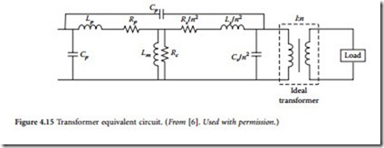
Equivalent circuits are often used to model the performance of transformers with greater accuracy. Although equivalent circuits are not exact replicas of real transformers, they are close enough to realize accurate results for most situations. The complete transformer equivalent circuit is shown in Figure 4.15.
The leakage inductance of both coils has been modeled by an inductor in series with the load, because the current in the coils also produces the leakage flux. These inductances are labeled Lp and Ls, respectively. Notice that the leakage inductance for the secondary side has been divided by the turns ratio n2 because it was reflected to the primary side. Resistors Rp and Rs are placed in series with the load to rep- resent the resistance of the conductors used to wind the coils. Again, the secondary resistance is divided by the square of the turns ratio because it was reflected.
The mutual inductance is represented by shunt inductor Lm, because the magnetizing current is not coupled to the load. Resistor Rc is also placed in shunt to represent the core loss resulting from hysteresis and eddy currents in the core. The stray capacitances between turns of the coils are represented by a capacitor connected across each pair of terminals. This capacitance is larger for coils with more turns. Although the capacitance is actually distributed, it is lumped for the equivalent circuit, in order to simplify the analysis. The capacitance from one coil to the other is represented by another capacitor placed in parallel with the leakage inductance and resistance.
The transfer function of the complete equivalent circuit is quite complex. For this reason, the equivalent circuit is often broken up into several equivalent circuits, each of which is valid only for a certain set of operating conditions. In the low-fre- quency range, the transformer acts like a highpass filter. (See Figure 4.16.) Above the corner frequency, the output voltage is nearly equal to the input volt- age. Below the corner frequency, the output voltage
is substantially smaller than the input voltage because of the presence of shunt inductor Lm. The distributed capacitances and leakage inductances can be largely neglected.
Application Considerations
Transformers are the most common pieces of equipment found in utility substations and distribution systems. Different types of transformers are used for varied purposes, from voltage level changes to phase angle regulation [7]. Because the primary circuits of distribution systems are designed for high voltages (in order to increase their load-carrying capability), the voltage must be stepped down at the consumer service entrance.
Transformers can be classified as distribution transformers and power transformers. The former type normally steps down voltages from primary voltage levels, such as 2,400, 4,160, or 13,800 V, to 120 or 240 V. These devices are almost always located outdoors where they are hung from crossarms, mounted on poles directly, or placed on platforms or in underground vaults. Power transformers are larger in size than distribution transformers and usually have auxiliary means for cooling. These transformers are typ- ically installed at distribution substations for stepping down voltages from the subtransmission levels of and 69 kV to primary distribution levels of up to 13.8 kV.
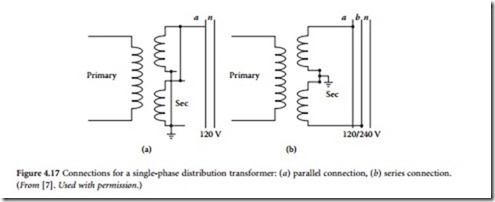
Single-phase distribution transformers typically have one high-voltage primary winding and two low-voltage secondary windings, which are rated at a nominal 120 V. The secondary coils may be connected in parallel to supply a two-wire 120 V circuit, shown in Figure 4.17a, or in series to supply a three-wire 120/240 V single circuit, shown in Figure 4.17b. As seen in the figures, one leg of the 120 V two-wire system and the middle leg of the 120/240 V three-wire system are grounded to limit the voltage to ground on the secondary side. In general, the 120/240 V three-wire connection is preferred because it has twice the load capacity of the 120 V system with only a 1.5 times increase in conductor size. Each 120 V winding has one half the total kilovoltampere rating of the transformer. The loads on the secondary side of the transformers are kept as balanced as possible, such that maximum transformer capacity can be utilized, and the neutral current kept to a minimum.
A three-phase transformer bank can be easily created by using three single-phase transformers. The two sides of these three transformers can be either connected in a wye or a delta configuration, thus allowing four possible types of connections. These are
• Wye-wye. With the wye-wye (Y-Y) connection, the secondary side is in phase with the primary circuit, and the ratio of primary to secondary voltage is the same as the ratio of turns in each of the phases. A possible connection is shown in Figure 4.18. Power distribution circuits supplied from a wye-wye bank often create series disturbances in communication circuits (e.g., telephone interference) in their immediate vicinity. One of the advantages of this connection is that when a system is changed from a delta to a four-wire wye to increase system capacity, existing transformers can be used.
• Wye-delta. In the Y-Δ connection, there is a 30° phase angle shift between the primary and secondary sides. The phase angle difference can be made either lagging or leading, depending on the external connections of the transformer bank. The case with the primary side lagging is shown in Figure 4.19, and the case with the primary side leading is shown in Figure 4.20. The transformation ratio is times the ratio of turns in each of the phases.
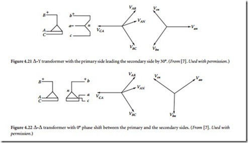
Delta-wye. With the Δ-Y connection, the neutral of the secondary wye can be grounded and single-phase loads connected across the phase and the neutral conductor. Three-phase loads are connected across the phases. The phasor relationship between the primary and the secondary sides is shown in Figure 4.21. The transformation ratio is 1/ phases.
• Delta-delta. The Δ-Δ connection does not cause a phase shift between the primary and the secondary sides. The phasor relationship of this transformer is shown in Figure 4.22. The transformation ratio is equal to the ratio of the turns in each of the phases. There is no problem from third-harmonic overvoltage or telephone interference because such disturbances get trapped in the delta and do not pass into the lines.
Although these four configurations are the most common ones used, other arrangements are possible, including:
• Open-delta. An advantage of the Δ-Δ connection is that if one of the single-phase transformers becomes damaged or is removed for maintenance, the remaining two can be operated in a so-called open-delta connection. Because the currents in each of the two remaining transformers are the same as the line current, each transformer carries closed-delta connection. The open-delta bank continues to deliver three-phase currents and volt- ages in their correct phase relationship. To keep the transformers from being overloaded, however,
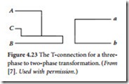
transformer, has an 86.6% tap. The main transformer is connected between two primary lines, whereas the teaser transformer is connected from the center tap of the main transformer to the third primary line. The secondary sides of the transformers provide two-phase service. A T- connection is shown in Figure 4.23.
