Description of the PF Test Equipment
PF and DF Test Set
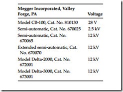
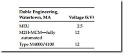
There are several manufacturers of the PF/DF test equipment. However, there are two main suppliers of PF/DF instruments in the United States, and they are Megger Incorporated, Valley Forge, Pennsylvania and Doble Engineering, Watertown, Massachusetts. The test sets listed below are in use for performing PF/DF tests on electric power system apparatus.
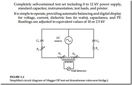
This section briefly describes the Megger DF test equipment, its theory, and its operation for performing PF tests. The description of theory and opera- tion for all types listed are essentially the same. A transformer ratio-arm bridge circuit is used as shown in the simplified diagram of Figure 3.2.
The circuit consists of a standard reference capacitor (CS) and the insula- tion under test (CX). A special multiwinding transformer is the characteristic feature of the circuit. A voltage is applied to both CS and CX. The ratio arms, NS and NX are adjusted to balance capacitive current, and the variable resis- tor (RS) is adjusted to balance resistive current. The null indicator is used to determine when the bridge circuit is balanced. The values of NS and NX are used to determine capacitance and the value of RS correlates to power (dissipation) factor of the test insulation.
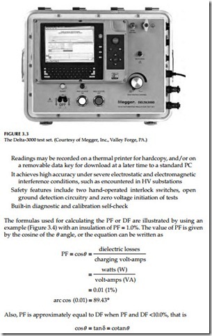
Model CB-100 is a low voltage (LV) bridge which is manually balanced for both capacitance and DF, but it is direct reading. The semiautomatic models require manual balancing for capacitance, but they provide a direct digital readout of DF. Model Delta-3000 is automatic balancing for both capacitance and PF, and can also display DF directly (Figure 3.3).
Some of the major features of the Delta-3000 test set are listed below:
Completely self-contained test set including 0 to 12 kV power supply, standard capacitor, instrumentation, test leads, and printer It is simple to operate, providing automatic balancing and digital display for voltage, current, dielectric loss (in watts), capacitance, and PF. Readings are adjusted to equivalent values of 10 or 2.5 kV
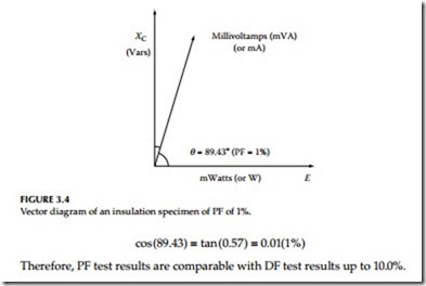
Therefore, PF test results are comparable with DF test results up to 10.0%.
General Instructions for the Operation of the Megger Test Set
1. Assemble the test set in accordance with the operating instruction manual.
2. Connect ground lead from the test set to a station ground.
Caution: PF tests are performed only on de-energized and isolated apparatus. Verify the equipment is cleared before attempting to connect leads.
3. Prepare the specimen for testing. This may include removing external connections, shorting winding terminals, etc.
4. Connect test leads: first to the test set, then to the apparatus to be tested following the instructions in the operating manual.
5. Check operation of safety and ground interlocks if supplied on the test set.
6. Select the proper test configuration for the insulation to be measured.
7. Initiate voltage output from the test set. Raise output voltage to the desired level.
8. Continue operation of the test set to obtain test readings, following the specific instructions in the operating manual.
a. For manual test sets, balance the bridge for capacitance and PF.
b. For semiautomatic test sets, balance the bridge for capacitance.
c. For automatic test sets, select measure to initiate automatic balancing.
9. Reduce voltage to zero, or lowest setting and deinitiate voltage output.
10. Record all values as provided by the test set: test voltage, current, watts-loss, capacitance, and PF.
For specific operating instructions for any Megger test set, the reader is advised to follow the instructions given in the appropriate test set operating manual.
Doble PF Test Set
This section briefly describes the Doble Engineering Company test equip- ment, its theory, and operation for performing PF tests. The description of theory and operation is based on the MEU test set, but the theory and opera- tion of the other test sets is the same for all test sets as manufactured by Doble Engineering. The type MEU test set has special measuring circuit in which the total current (IT) of the insulation specimen is measured. Then a balancing network is switched into the measuring circuit and the capacitive component (IC) of the specimen current is balanced out. The in-phase compo- nent (IR) of the specimen current is then measured.
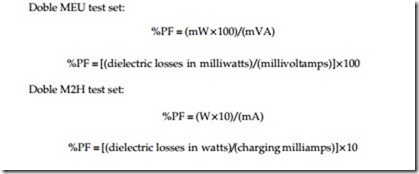
The formulas used for calculating the PF or DF are illustrated by using the example of Figure 3.4 with an insulation of PF of 1.0%. The value of PF is given by the cosine q, or the equation can be written as given below for the
2.5 kV MEU and 10 kV M2H test set:
The following is a set of general instructions which describe the procedure for operating the Doble test sets:
1. Assemble test set in accordance with the instruction book.
2. Check the ground and the HV connections and safety switches.
3. Connect specimen for the desired test. Raise test voltage to desired level.
4. Adjust the meter reading to full scale. The test set is ready to use and to record the test current and dielectric loss for the specimen.
5. Measure total charging current as the product of the meter reading and a multiplier within the proper range.
6. Specimen loss is measured by turning the milliwatts-adjust which cancels the capacitive reactance. When the capacitive reactance is cancelled the meter will be at minimum reading. This meter reading and the proper multiplier provides the milliwatt for the dielectric loss in the insulation.
7. The capacitance of the specimen is automatically obtained as a prod- uct of capacitance multiplier and capacitance dial reading at mini- mum milliwatts balance.
8. The product of the meter reading and the meter multiplier is the mil- liwatts loss of the specimen.
9. The power supply polarity is reversed to cancel the effect of electro- static interference. The average of the two milliwatts results is calcu- lated as the specimen milliwatts loss.
10. The test set has shielding to minimize the effect of electrostatic interference, as well as electromagnetic interference. For cases where high interference is encountered, a special interference cancellation circuit is available with the 10 kV test sets from Doble Engineering. The more advanced design of the Doble M4000 test set does not require interference cancellation circuit.
