Ampacities
The ampacity is the maximum designed current of a conductor. This current carrying capacity is normally given in amperes. A given conductor has
several ampacities, depending on its application and the assumptions used. House and Tuttle (1958) derive the ampacity calculations described below, which are used in IEEE Std. 738-1993 and most other published ampacity tables (Aluminum Association, 1986; Southwire Company, 1994).
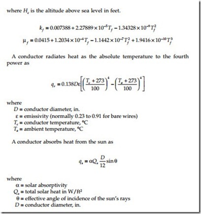
Sun, wind, and ambient temperature change a conductor’s ampacity. A conductor’s temperature depends on the thermal balance of heat inputs and losses. Current driven through a conductor’s resistance creates heat (I2R). The sun is another source of heat into the conductor. Heat escapes from the conductor through radiation and from convection. Considering the balance of inputs and outputs, the ampacity of a conductor is
The density, viscosity, and thermal conductivity of air all depend on tem- perature (actually the film temperature Tf near the surface of the conductor, which is taken as the average of the conductor and ambient temperatures). Tables of these are available in the references (IEEE Std. 738-1993; Southwire Company, 1994). We may also use the following polynomial approximations (IEEE Std. 738-1993):
The angles and total solar heat depend on the time of day and the latitude. Since the solar input term does not change the output significantly, we can use some default values. For a latitude of 30°N at 11 a.m. in clear atmosphere, Qs = 95.2 W/ft,2 and q = 78.6°.
Emissivity (e) is the ability of a conductor to radiate heat into the air. Absorptivity (a) quantifies how much heat a conductor can absorb. Emissivity and absorptivity are interrelated; a nice shiny conductor reflects away much of the sun’s heat but does not radiate heat well. Commonly, both are assumed to be 0.5 for bare wire. More conservative assumptions, possibly overconservative, are 0.7 for emissivity and 0.9 for absorptivity.
Some of the main factors impacting ampacity are
• Allowable conductor temperature — Ampacity increases significantly with higher allowed temperatures.
• Ambient temperature — Ampacity increases about 1% for each 1°C decrease in ambient temperature.
• Wind speed — Even a small wind helps cool conductors significantly.
With no wind, ampacities are significantly lower than with a 2-ft/
sec crosswind.
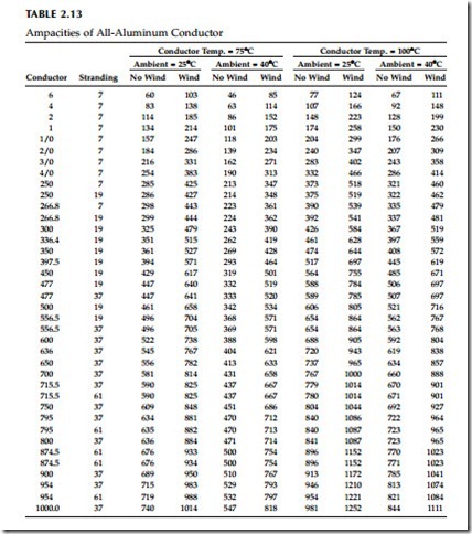
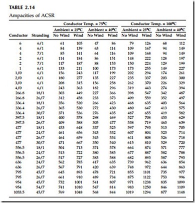
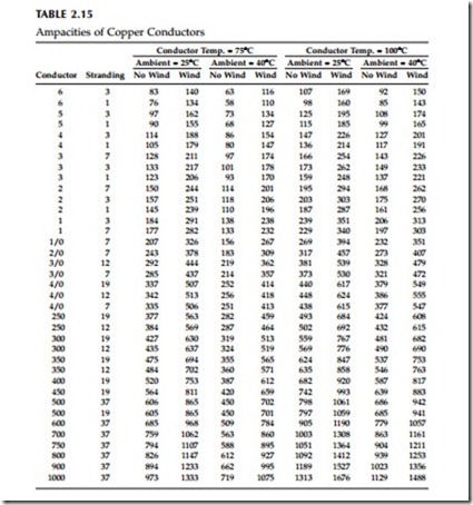
Table 2.13 through Table 2.15 show ampacities of all-aluminum, ACSR, and copper conductors. All assume the following:
• Emissivity = 0.5, absorptivity = 0.5
• 30°N at 11 a.m. in clear atmosphere
• Wind speed = 2 ft/sec
• Elevation = sea level
The solar heating input has modest impacts on the results. With no sun, the ampacity increases only a few percent.
Some simplifying equations help for evaluating some of the significant impacts on ampacity. We can estimate changes in ambient and allowable temperature variations (Black and Rehberg, 1985; Southwire Company, 1994) with
where Inew is the new ampacity based on a new conductor limit Tc,new and a new ambient temperature Ta,new. Likewise, Iold is the original ampacity based on a conductor limit Tc,old and an ambient temperature Ta,old.
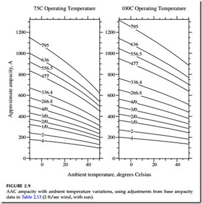
This approach neglects solar heating and the change in conductor resis- tance with temperature (both have small impacts). Doing this simplifies the ampacity calculation to a constant (dependent on weather and conductor characteristics) times the difference between the conductor temperature and the ambient temperature: I2 = K(Tc – Ta). We do not use this simplification for the original ampacity calculation, but it helps us evaluate changes in temperatures or currents.
We use this approach in Figure 2.9 to show the variation in ampacity with ambient conductor assumptions along with two conductor operating limits.
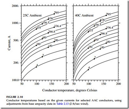
Also, Figure 2.10 shows the conductor temperature vs. loading for several AAC conductors. This graph highlights the major impact of operating tem- perature on ampacity. If we are overly conservative on a conductor limit, we end up with an overly restrictive ampacity.
We can also use the simplified ampacity equation to estimate the conductor temperature at a current higher or lower than the rated ampacity as (and at a different ambient temperature if we wish):
When examining a line’s ampacity, always remember that the overhead wire may not be the weakest link; substation exit cables, terminations, reclosers, or other gear may limit a circuit’s current before the conductors do. Also, with currents near a conductor’s rating, voltage drop is high.
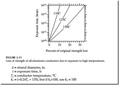
The maximum operating temperature is an important consideration. Higher designed operating temperatures allow higher currents. But at higher temperatures, we have a higher risk of damage to the conductors. Aluminum strands are strain hardened during manufacturing (the H19 in aluminum’s 1350-H19 designation means “extra hard”). Heating relaxes the strands — the aluminum elongates and weakens. This damage is called annealing. As aluminum anneals, it reverts back to its natural, softer state: fully annealed 1350 aluminum wire elongates by 30% and loses 58% of its strength (10,000 psi vs. 24,000 psi fully hardened). Even fully annealed, failure may not be immediate; the next ice load or heavy winds may break a conductor. Slow annealing begins near 100°C. Aluminum anneals rapidly above 200°C. Annealing damage is permanent and accumulates over time. Remaining strength for AAC conductors varies with conductor temperature and dura- tion of exposure as approximately (Harvey, 1971)
ACSR may be loaded higher than the same size AAC conductor. As the aluminum loses strength, the steel carries more of the tension. The steel does not lose strength until reaching higher temperatures.
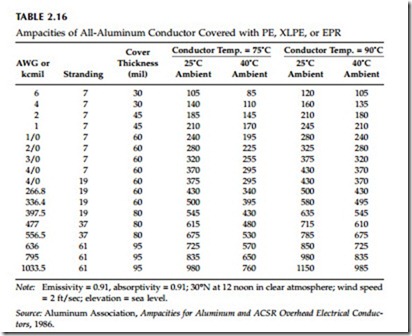
Covered conductors are darker, so they absorb more heat from the sun but radiate heat better; the Aluminum Association (1986) uses 0.91 for both the emissivity and the absorptivity of covered wire. Table 2.16 shows ampacities of covered wire. Covered conductors have ampacities that are close to bare- conductor ampacities. The most significant difference is that covered conductors have less ability to withstand higher temperatures; the insulation degrades. Polyethylene is especially prone to damage, so it should not be operated above 75°C. EPR and XLPE may be operated up to 90°C.
Some utilities use two ratings, a “normal” ampacity with a 75°C design temperature and an “emergency” ampacity with a 90 or 100°C design. Con- ductors are selected for the normal rating, but operation is allowed to the emergency rating. Overhead circuits have considerable capability for over- load, especially during cooler weather. We do not use relaying to trip “over- loaded” circuits. At higher temperatures, conductors age more quickly but do not usually fail immediately.
Neutral Conductor Sizing
Because the neutral conductor carries less current than the phase conductors, utilities can use smaller neutral conductors. On three-phase circuits with
balanced loading, the neutral carries almost no current. On single-phase circuits with a multigrounded neutral, the neutral normally carries 40 to 60% of the current (the earth carries the remainder).
On single-phase circuits, some utilities use fully rated neutrals, where the neutral and the phase are the same size. Some use reduced neutrals. The resistance of the neutral should be no more than twice the resistance of the phase conductor, and we are safer with a resistance less than 1.5 times the phase conductor, which is a conductivity or cross-sectional area of 2/3 the phase conductor. Common practice is to drop one to three gage sizes for the neutral: a 4/0 phase has a 2/0 neutral, or a 1/0 phase has a number 2 neutral. Dropping three gage sizes doubles the resistance, so we do not want to go any smaller than that.
On three-phase circuits, most utilities use reduced neutrals, dropping the area to about 25 to 70% of the phase conductor (and multiplying the resis- tance by 1.4 to 4).
Several other factors besides ampacity play a role in how small neutral conductors are:
• Grounding — A reduced neutral increases the overvoltages on the unfaulted phases during single line-to-ground faults (see Chapter 13). It also increases stray voltages.
• Faults — A reduced neutral reduces the fault current for single line- to-ground faults, which makes it more difficult to detect faults at far distances. Also, the reduced neutral is subjected to the same fault current as the phase, so impacts on burning down the neutral should be considered for smaller neutrals.
• Secondary — If the primary and secondary neutral are shared, the neutral must handle the primary and secondary unbalanced current (and have the mechanical strength to hold up the secondary phase conductors in triplex or quadraplex construction).
• Mechanical — On longer spans, the sag of the neutral should coordinate with the sag of the phases and the minimum ground clear- ances to ensure that spacing rules are not violated.
