MODERN GAS TURBINE DESIGN FOR POWER GENERATION
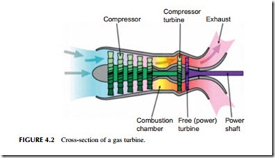
A modern gas turbine maintains the three principle components of the Stolze design: a compressor, a combustion chamber, and a turbine stage (Figure 4.2). As in that design, these are closely coupled with the two rotary components on the same axis. The main energy-producing component is the turbine stage
that, as outlined earlier, drives its own compressor as well as provides energy to turn a generator and produce electricity.
The turbine stage of a gas turbine is a thermodynamic heat engine. As with all heat engines, the efficiency of its operation depends on the amount of energy it can extract from the operating fluid (in this case air). For an ideal heat engine this in turn depends on the temperature and pressure difference between the gas entering the engine inlet and the gas at the turbine exhaust.
It is in the operation of the turbine stage that aero engines and power generation turbines diverge. An aero engine only needs the turbine to produce sufficient rotary power to drive its compressor. All the rest of the energy within the gas should be delivered through the turbine exhaust as a high-pressure flow of gas providing thrust. For a power generation turbine, as much energy as possible should be captured in the turbine rotary motion and as little energy as possible should exit through the turbine exhaust, which should release gases at the lowest temperature and pressure possible.
The input energy for the turbine depends on both temperature and pressure of the air at the turbine inlet. The pressure is a design feature that will vary from manufacturer to manufacturer and is defined by the compression ratio chosen for the design. All modern gas turbines utilize axial compressors that draw in and compress air. These comprise several stages of blades (much like a series of windmills but operating in reverse) to compress air to between 15 and 30 times atmospheric pressure, depending on the design (i.e., the compression ratio is between 15:1 and 30:1). A modern unit might have 10–12 sets of compressor blades (also called stages). Efficiency is typically 87%.
High-pressure air from the compressor then enters a combustion chamber where it is mixed with fuel and ignited, increasing the temperature of the air to as high as 1600 oC. At temperatures this elevated, nitrogen from air is easily oxidized to produce nitrogen oxides, which will then appear in the gas turbine exhaust. Since nitrogen oxide emissions must be controlled, gas turbine combustion chambers are designed to maintain reducing conditions as far as possible, with staged combustion to limit the production of nitrogen oxide. In some cases water is injected into the combustion chamber to reduce nitrogen oxide levels but most large turbines use dry combustion chambers.
Combustion chambers come in a variety of designs and dispositions. In some gas turbines they are kept separate from the turbine body. Other designs position them within the body, between compressor and turbine stages, while in others there are multiple combustion chambers arranged annularly around the body of the turbine. At least one manufacturer uses sequential combustion similar in concept to reheat in a steam turbine. In this case the turbine stage of the unit is split into two parts and the hot gases exiting the first part pass into an additional combustion chamber where further fuel is ignited to increase temperature and pressure again before entering the second part.
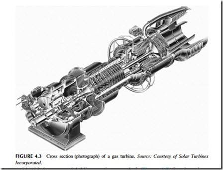
The turbine stage of a modern gas turbine will normally comprise three to five stages of blades (windmills operating as windmills in this case) operating with an efficiency of around 89%. Some designs have both compressor and
turbine blades mounted rigidly onto the same shaft (Figure 4.3). In others there are two concentric shafts—one carrying the compressor blades and the first one or two turbine stages. These turbine stages power the compressor while the lat- ter stages, on a second shaft, are attached to a generator and produce power. Some aero-derivative gas turbines take this complexity a stage further with the compressor also divided into two parts too—a low-pressure compressor and a high-pressure compressor. The low-pressure compressor is driven by the low-pressure turbine stage of the unit and, via a concentric shaft, the high-pressure turbine drives the high-pressure compressor.
The exhaust gases from a simple gas turbine generator are released to the atmosphere. For the most efficient aero-derivative gas turbine, the outlet gas temperature will be around 400 oC to 500 oC. This represents a significant energy loss. Even so, such units can be relatively efficient. In fact, these aero-derivative gas turbines are usually the most efficient of all gas turbines with the best recording an energy conversion efficiency of 46%. Power output from this type of turbine is usually under 100 MW. Small industrial turbines tend to have slightly lower efficiencies, up to 42%.
For an open-cycle gas turbine (i.e., one not operating in a combined cycle plant), lower exhaust gas temperature equates to higher efficiency, which in turn equates to better economy. In a combined cycle plant, on the other hand, a higher exhaust gas temperature is usually preferable because this allows the second part of the plant, based on a steam turbine, to operate more efficiently. Thus, most of the largest industrial gas turbines that are principally designed for combined cycle operation will actually have a lower efficiency in open-cycle mode than some smaller turbines to obtain the best efficiency in combined cycle mode. The largest industrial gas turbines have efficiencies between 38% and 42%.

