Short-Circuit Considerations and Power Circuit Breaker Ratings
To understand the rating basis of power circuit breakers, it is important to understand how the circuit breaker will perform under conditions where the short-circuit current varies with time. The rating structure of a power circuit breaker is complicated because of the opening time of the circuit breaker during a short-circuit condition. The total operating time of the circuit breaker is based on the following:
• Protective relay operation time
• Circuit breaker operation time
The protective relay operation time is a function of relay type and its setting. The types of relays and their operating characteristics are discussed in Chapter 9. The breaker operation time (i.e., mechanical time) consists of the following:
• Circuit breaker trip coil to energize its operating mechanism
• Circuit breaker contact parting time
• Circuit breaker to quench the arc in the arc chamber (or in the vacuum bottle in case of vacuum interrupters)
High mechanical stresses are produced instantaneously in the circuit breaker during the interruption of a short circuit. These stresses vary as the square of the current and are greatest at maximum current. The fault current magnitude varies from short-circuit inception to the time when it reaches a steady-state condition. This variation depends on the instantaneous value of the system voltages at the instant the fault occurs, also known as the closing angle; the dynamic change in alternating current (AC) impedance as the energy balance changes and the decay in the direct current (DC) component of the fault current. Consequently, the circuit breaker interrupts the fault current at some time (usually a few cycles) after the short circuit occurred. Therefore, power circuit breaker ratings are established on two bases:
• Momentary rating, that is, circuit breaker ability to close and latch on the maximum short-circuit current available without mechanical damage.
• Interrupting rating, that is, circuit breaker ability to interrupt the flow of fault current without mechanical damage.
The fault current is highly asymmetrical from the time of fault inception to several cycles later. It becomes symmetrical after it reaches steady-state con- ditions. To understand fully the varying phenomena of short-circuit current, let us briefly review short-circuit definitions and the kinds of current avail- able in a fault.
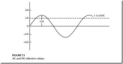
Root–mean-square (rms) (effective) value: This is an effective value of AC and is usually expressed as 0.707Im, where Im is the AC peak value. This rms current value is shown in Figure 7.1.
Peak value (crest): This is the maximum value of the AC wave peak.
Average value: The average value of an AC wave is zero because the positive and negative loops have the same area. However, the average value of the posi- tive loop of a symmetrical wave can be expressed in terms of peak value. For sine wave the average value is expressed as 0.636Im, where Im is the peak value.
Instantaneous (momentary) value: It is difficult to manipulate analytically the instantaneous value of alternating wave forms. In general, for short-circuit considerations the instantaneous value (or momentary value) is the peak value of the sine wave occurring at first half-cycle.
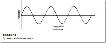
Symmetrical current: A symmetrical current wave is symmetrical about the time axis (zero axis) of the wave. This is shown in Figure 7.2.
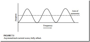
Asymmetrical current: An asymmetrical current wave is not symmetrical about the time axis. The axis of symmetry is displaced or offset from the
time axis. This is shown in Figure 7.3. An asymmetrical wave can be partially offset or fully offset. Offset waves are sometimes called displaced waves.
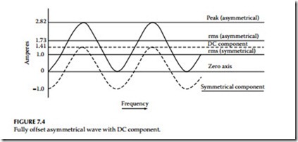
DC component: The axis of symmetry of an offset wave resembles a DC, and symmetrical currents can be readily handled if considered to have an AC and a DC component. Both of these components are theoretical. The DC component is generated within the AC system and has no external source. Figure 7.4 shows a fully offset asymmetrical current with a steady DC com- ponent as its axis of symmetry. The symmetrical component has the zero axis as its axis of symmetry. If the rms or effective value of the symmetrical current is 1, the peak of the symmetrical current is 1.41. This is also the effective value of the DC component. We can add these two effective currents together by the square root of the sum of the squares and get the effective or rms value of asymmetrical current.
The rms value of a fully offset asymmetrical current is 1.73 times the symmetrical rms current. It is readily apparent that the peak asymmetrical current is twice the peak symmetrical current: 2 × 1.41 = 2.82.
Total current: The term total current is used to express the total or sum of the AC and DC components of an asymmetrical current. Total current and total asymmetrical current have the same meaning and may be expressed in peak or rms amperes.
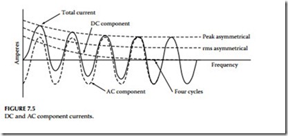
Decay: Unfortunately, fault currents are neither symmetrical nor fully asymmetrical but somewhere in between. The DC component is usually short-lived and decays after several cycles. In Figure 7.5, the DC compo- nent decays to zero in about four cycles. The rate of decay is called decre- ment, and depends upon the circuit constants. The DC component would never decay in a circuit having reactance but zero resistance and would remain constant forever. In a circuit having resistance but zero reactance, the component would decay instantly. These are theoretical conditions; all practical circuits have some resistance and reactance, and the DC compo- nent disappears in a few cycles. In practice when performing short circuit analyses the X/R ratio is computed to give a practical estimate for determining how quickly the DC component will decay. For more detail, see definition of X/R in this chapter.
Closing angle: A short-circuit fault can occur at any point on the voltage wave. So far we have avoided discussing voltage characteristics, but the volt- age wave resembles the current wave. The two waves may be in phase or out
of phase, and the magnitude and symmetry of the current wave of a short circuit depends on the point on the voltage wave at which the fault occurs. This is known as the closing angle of the fault.
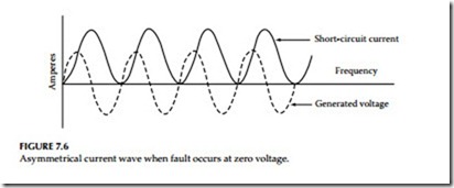
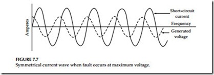
Random closing: In real life, faults occur at any and every point on the volt- age wave. In a laboratory, this can be duplicated by closing the circuit at random. This is known as random closing. The following is true of a short circuit having negligible resistance:
• If the fault occurs at zero voltage, the current wave is fully asym- metrical, as shown in Figure 7.6
• If the fault occurs at maximum voltage, the current wave is com- pletely symmetrical, as shown in Figure 7.7
Most natural faults occur somewhere in between these two extremes.
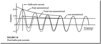
Available short circuit (first half-cycle current): What is the available short-circuit current value of a wave that is neither symmetrical nor asymmetrical? Referring to Figure 7.8, the current wave is symmetrical about four cycles after the DC component becomes zero. We can also determine the total rms asymmetrical current at one, two, or three cycles or at any other time after the short circuit started. The accepted practice is to use the current that is available one half- cycle after the short circuit starts. For a fully offset wave, the maximum current
does occur at the end of the first half-cycle of time. Because this is the worst case, we should determine the peak and rms currents at this point.
As already mentioned, the rate of decay depends upon the circuit constants. A study of actual circuits of 600 V or less indicates that the proper half-cycle value for rms asymmetrical current is 1.4 times the rms symmetrical current, and the peak instantaneous current is 1.7 times the rms asymmetrical current. Half-cycle available current is 1.7 × 1.4 = 2.4 rms symmetrical current.
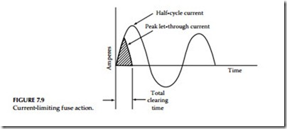
Current limitation: Current-limiting fuses and circuit breakers do not allow the short-circuit current to reach the full available value. They interrupt the circuit in less than one half-cycle before the current builds up to the maxi- mum value. The various times associated with fuses are the following:
• Melting time:
• Arcing time:
Time required to melt the fusible link
Time required for the arc to burn back the fusible link
and reduce the current to zero
• Total clearing time:
Total clearing time
Let-through current: The maximum instantaneous or peak current that passes through the fuse is called the let-through current. This can be expressed in rms amperes, also.
Triangular wave: The rise and fall of the current through a current-limiting fuse resembles an isosceles triangle, and can be assumed to be a triangle without introducing appreciable error. Since this is not a sine wave, the rms value of the let-through current cannot be determined by taking 0.707 of the peak value as is done for a sine wave. The effective or rms value of a triangular wave is equal to the peak value divided by 3.
The let-through current of a current-limiting fuse varies with the design, ampere rating, and available short-circuit current. Fuse manufacturers furnish let-through curves for the various types of current-limiting fuses.
Three-phase short circuit: Three-phase short-circuit currents can be deter- mined in exactly the same way as single-phase currents if we assume the three phases are symmetrical. The three phases have different current values at any instant. Only one can be fully asymmetrical at a given time. This is called the maximum or worst phase, and its rms current value can be found by multiplying the symmetrical rms current by the proper factor. The currents in three phases can be averaged, and the average three-phase rms amperes can be determined by multiplying the symmetrical rms current by the proper factor, which is determined by the X/R ratio of the power system.
X/R ratio: Every practical circuit contains resistance (R) and inductive reac- tance (X). These are electrically in series. Their combined effect is called impedance (Z). When current flows through an inductance (coil), the voltage leads the current by 90°, and when current flows through a resistance, the voltage and current are in phase. This means that X and R must be combined vectorially to obtain impedance. The impedance triangle relating X, R, and Z is shown in Figure 7.10.
The resultant angle q is the angle between the voltage and current waves and is called the phase angle. The voltage leads the current or the current lags the voltage by an amount equal to the phase angle. The asymmetrical current may be obtained from known symmetrical current by multiply- ing with a multiplying factor for a known X/R ratio. The multiplying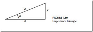
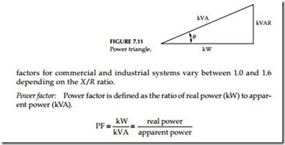
Kilowatts are measured with a wattmeter. Kilovolt-amperes are determined with a voltmeter and an ammeter, and the voltage and current waves may be in phase or out of phase. The relationship of kilowatts, kilovars, and kilovolt- amperes is shown in Figure 7.11.
Power circuit breaker rating: The ANSI ratings for power circuit breakers are expressed by two rating structures. The older standard ANSI C37.6 expresses the interrupting rating of AC high-voltage (HV) breakers megavolt-amperes (MVA) based on total or asymmetrical current at the time of contact parting. The newer standard ANSI C37.06, which was introduced in 1964, expresses the interrupting of AC HV breakers based on total rms symmetrical currents at the time of contact parting. The rating and characteristics of the ANSI C37.06 and ANSI C37.6 are shown in Tables 7.3 and 7.4, respectively.
The standards define that a circuit breaker shall be capable of performing the following in succession:
1. Close and immediately latch at normal frequency current, which does not exceed its momentary capability
2. Carry its maximum rated symmetrical current at specified operating voltage for duration of its rated permissible tripping delay
3. Interrupt all currents not greater than its rated symmetrical interrupting current at a specified operating voltage and its related asymmetrical current based on its rated contact parting time
The typical short-circuit current consists of the following:
1. Symmetrical AC wave shape
2. DC component
3. Total current
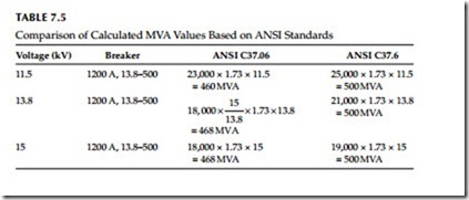
Let us now compare the rating structure of the two standards by making calculations for a 13.8 kV, 1200 A, 500 MVA rated breaker. The calculations for short-circuit interrupting MVA capability using ANSI C37.06 and C37.6 are made for power circuit breakers operating at minimum, nominal, and maximum voltages. These values are shown in Table 7.5.
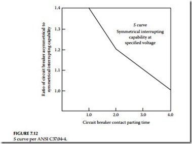
It is interesting to note from Table 7.5 that the maximum interrupting MVA calculated based on ANSI C37.06 is less than the MVA rating based on ANSI C37.6. The MVA based on ANSI C37.06 also varies for different operating voltages as compared to ANSI C37.6 MVA values. The standards committee developing new standards developed a more stringent basis for the short circuit ratings as stated in ANSI C37.06, 2000. The emphasis under the ANSI C37.06 is to rate the circuit breakers in rms amperes rather than MVA, as is the case in the ANSI C37.6. The rms symmetrical rating system is based on the symmetrical component of the short-circuit current at the time of contact opening. Since the short-circuit current is varying from fault inception until it reaches steady-state conditions, some fixed relationship must be defined (or calculated) between symmetrical and asymmetrical currents based on breaker opening time. This fixed rela- tionship is defined in ANSI C37.04-4.5.2.2 by the S curve, which is shown in Figure 7.12.
In summary, the ANSI C37.06 standard requires that the proper breaker should be selected by calculating the total symmetrical rms current at contact parting time. The reason for selecting the contact parting time as the basis of fault interrupting rating is that the breaker should be able to withstand the high mechanical stresses imposed upon it by the first half-cycle fault current, if the breaker is closed in on a fault. The contact parting time of a circuit breaker is the sum of one half-cycle tripping delay plus the operating time of the circuit breaker. For breakers rated at eight, five, three, and two cycles of interrupting time, the related stan- dard contact parting times are four, three, two, and one and a half cycles, respectively.
Selection and Application of Power Circuit Breakers
The application of power switchgear is relatively a simple procedure in most cases whether the switchgear is metal-clad or fused interrupter switches. The following steps are usually considered in applying this equipment:
• Selection of switching scheme
• Calculation of available fault current for breaker or fused interrupter selection
• Main bus continuous current rating selection
• Current and potential transformer selection
• Protective relay selection
• Circuit breaker control power selection
• Other special considerations
Many different switching schemes are available in power switchgear to meet the desired reliability or operational flexibility. A choice should be made based on system requirements, maintenance considerations, reliability, and future expansion.
The selection of the power circuit breaker or fused interrupter switch involves the calculation of available fault current for interrupting duty pur- poses. Insofar as the interrupting of the circuit breaker is concerned, the following limits should not be exceeded:
• Interrupting rms symmetrical amperes between the operating voltage limits.
• Total fault current that is available at contact parting time in terms of symmetrical rms amperes.
• Momentary current that is available during the first half-cycle. The standards allow the momentary rating of circuit breakers to be 1.6 times the rms interrupting rating at an X/R ratio of 10. In general industrial systems, where X/R ratios can approach 15–20, the next higher (standard) interrupting duty may have to be applied even though the RMS sym- metrical currents may be similar to those where the X/R is 10 or less.
• The continuous current that the breaker is rated to carry.
• The operating voltage limits, that is, the minimum and maximum design voltages of the circuit breaker.
• The breakers used for reclosing or repetitive duty should be derated in accordance with NEMA SG 4-2005 standards in order to be applied properly.
