Inline pumps
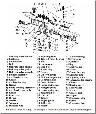
The parts breakdown for a Bosch size A Series PE inline pump for six-cylinder engines is shown in Fig. 5-3. Shims (21 and 49) establish camshaft float. Two fuel- delivery adjustments are provided. The basic setting is determined by the height of
the adjustment bolts (35) that thread into the tops of each tappet. In addition, friction clamps (29) permit the control-sleeve pinions (30) to move relative to the rack to compensate for tooth wear and production tolerances. Fuel-delivery adjustments for this and all other injection pumps must be made on a test stand.
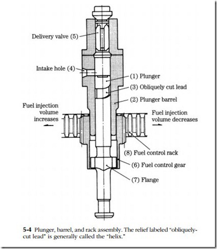
The drawing of a single-plunger pump in Fig. 5-4 helps to clarify the relation- ship between the rack, fuel control gear (plunger pinion), and plunger. Fuel enters through the intake port on the right and exits past the delivery valve at the top of the unit. The obliquely cut groove on the plunger outer diameter (OD) functions in conjunction with the rack to throttle fuel delivery.
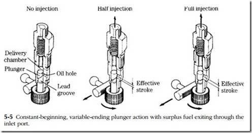
How this is done is shown in Fig. 5-5. At the bottom of the stroke, the plunger uncovers the inlet port. Fuel enters the pressure chamber above the plunger. The plunger rises, initially pushing fuel back out the inlet port. Further movement masks the inlet port. The plunger continues to rise, building pressure on fuel trapped above it. The delivery valve opens, and a few milliseconds later, the injector dis- charges. Fuel continues to flow until the annular groove milled along the side of the plunger uncovers the inlet port. At this point, pressure bleeds back through the inlet port and injection ceases. Because of the shape of the groove, rotating the plunger opens the inlet port to pressure earlier or later in the plunger stroke.
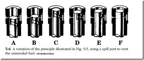
American Bosch, Robert Bosch, and CAV barrels are drilled with a second port above the inlet port to accept spillage during part-throttle operation. Figure 5-6 illustrates the metering action of a CAV pump. Fuel enters the barrel at A and continues to flow until plunger movement masks the two ports (inlet shown on the left, spill port on the right). At full load, the pressure bleed-down through
the spill port is delayed until the plunger approaches the end of its stroke, as shown in drawing C. You might wonder why the spill port opens before top dead center (tdc), when a few more degrees of cam movement would raise fuel pres- sure even more. The reason is that cam-driven plungers behave like pistons, accelerating at mid-stroke and slowing as the dead centers are approached. Opening the spill port early, while plunger velocity and pressure rise are rapid, terminates injection far more abruptly than if the port remained closed until the plunger reached tdc.
In drawing D, the annular groove has rotated to the half-load position. The effects of further rotation are shown at E, which represents idle, and at F, shutdown.
However the porting is arranged, the effective stroke has a constant beginning and a variable ending for pumps this book is concerned with. Some marine and large stationary engines meter fuel delivery at the beginning of the stroke.
Details of the mechanism for transmitting rack movement to the plungers vary with the manufacturer, but always include an adjustment to equalize delivery between plunger assemblies. At a given rack position, each cylinder must receive the same amount of fuel.
