Uninterruptible Power Supply Commissioning and Testing
Background
It cannot be guaranteed that an electrical power supply that is free from voltage and frequency variations is going to be available during all times. The occurrence of faults or other electrical anomalies in the users’ installations or in the utility distribution system is undeniable and unpre- dictable. Since data centers for information technology (IT) and other high- technology companies’ installations are particularly sensitive to power supply fluctuations and distortions, they typically rely on an uninterruptible power supply (UPS) for clean power and as well as for backup or standby power. Some installations even include a second UPS supplied by a separate feeder, and a standby generator that can be set to start automatically few minutes after detecting a power interruption. If the risk from weather or other local occurrences is great enough, some facilities will manually switch
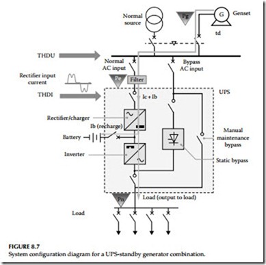
over to backup generation, ahead of time. Figure 8.7 illustrates a typical UPS-standby generator system configuration for supplying backup power to critical installations. To assure that the UPS system will function as designed, the following tests should be performed during installation and then periodically (monthly or quarterly, depending on contractual agree- ments) after the system is commissioned. Tests during installation phase are divided into two stages:
1. Preinstallation (or commissioning)—test before connecting the criti- cal loads
2. Combined—connect critical loads and test while cutting standby generator in and out
Preinstallation Checks and Tests
UPS functional and alarms tests: The purpose of this test is to check the UPS functionality, LED display, and alarm messages.
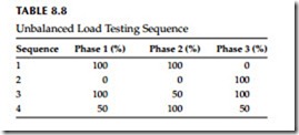
UPS specification test: The purpose of this test is to check the UPS specifications to ensure that the installed equipment meets the hardware and functional requirements. Perform the test using two three-phase power ana- lyzer instruments, such Fluke 435s, or equal. The procedure is outlined as follows: record voltage, current, real power, apparent power, power factor, voltage, and current total harmonic distortion (THD) at both the input and output. Vary the loads from 0% to 100% in 25% steps for balanced load test- ing. For unbalanced load testing, follow the load matrix shown in Table 8.8.
UPS burn-in test: The purpose of this is to verify that the UPS system can operate at the rated load under ambient room temperature conditions. Procedure: Load the UPS to rated load and operate for 8–24 h, depending on contractual requirements. Monitor phase currents, voltages, power, and attri- butes mentioned earlier including the temperature.
UPS step load and bypass loss transient tests: The purpose of this test is to demonstrate the transient response of the UPS module. During this test, the three phase voltage should remain stable and not vary much despite the changes in load current. Record data and compare against specification for deviations. Procedure: Measure UPS transient response for
1. 0% to 100% to 0% load steps
2. 0% to 50% to 0% load steps
3. 50% to 100% to 50% load steps
4. UPS running with loss of bypass mains
UPS start and stop test: The purpose of this test is to demonstrate the correct operation when the UPS is switched on and off with full load.
Procedure: With the module running at 50% and 100% load, switch the inverter OFF and ON. Record transients, load voltage, load current, mains 2 current, and mains 1 current.
UPS full load battery discharge test: The purpose of this test is to demonstrate the correct UPS operation for the time duration of the UPS batteries (such as 15 min) at full load during a power failure.
Procedure: Measure battery cells before and after discharge using a battery monitoring system.
UPS loss and return of mains test: The purpose of this test is to demonstrate the correct operation during loss and return of the mains.
Procedure: Run module at normal load and switch the UPS main input ON and OFF. Record transients, load voltage, load current, and mains 1 current.
UPS loss and return of battery test: The purpose of this test is to demonstrate the correct operation during loss and return of UPS batteries.
Procedure: Run module at normal load and switch the UPS main battery breaker ON and OFF. Record transients, load voltage, load current, and mains 1 current.
UPS load transfer test: The purpose of this test is to demonstrate the correct operation during load transfer.
Procedure: Run module at normal load and switch UPS OFF and ON until the load is on static bypass. This procedure is reversed from static bypass to UPS. Record load voltage, load current, and bypass current.
UPS transfer to bypass and back test: The purpose of this test is to demon- strate the correct operation with external bypass.
Procedure: Transfer the load to external bypass and back to UPS. Record load voltage and load current.
Combined Test (UPS with the Generator)
Connect the critical loads and standby generator and repeat the same tests discussed above at 0% and 100% load conditions. Monitor transfer between the mains supply, UPS, and standby generator to ensure that transients and waveform distortion stays within acceptable limits.
Maintenance Test
Conduct periodic (monthly) maintenance tests throughout the life of the UPS- generator power supply system. Follow the combined test procedure for every- thing except the standby generator—it may not need to be tested as frequently as the other components of the UPS system including its battery system.
UPS Battery System
In a critical power system, knowing and understanding the condition of a stationary battery is important. Inspection and testing of the battery system should be undertaken to assess the following:
• Interconnection integrity
• State of charge
• The overall correctness of the installation
• Benchmark values for comparison to future tests
• Data to aid troubleshooting when performance is less than designed or anticipated
If basic information is not collected, analyzed, and understood before initial charging and dynamic testing, the results are unpredictable. There is a very real possibility that the battery could suffer damage if a major problem is not diagnosed in advance. Some possible consequences are
• Terminal failure due to loose connections
• Reduced capacity due to incomplete state of charge
• Damaged cells due to incorrect polarity orientation
• High connection resistance due to incorrectly prepared mating surfaces
• Schedule delays and extra costs to replace or repair damaged items
A correctly performed inspection, therefore, is very important for assuring battery reliability.
Battery System Inspection
The procedures, processes, and methods discussed here focus on the vented lead–acid stationary battery installed on racks. The smaller valve- regulated lead–acid (VRLA) batteries normally installed in cabinets may be inspected in the similar manner. Battery system installation inspections can be performed by the installing contractor, by a third-party battery ser- vice provider or by the battery manufacturer ’s authorized representatives. The completed inspection report should be available to those responsible for the battery and thoroughly reviewed. Any necessary corrective action as a result of the inspection should be carried out before the battery receives its initial charge.
The inspection of the battery system is performed in three areas:
1. Mechanical inspection
2. Precharge electrical inspection
3. Electrochemical inspection prior to load testing
Mechanical inspection
These steps should be carried out prior to initial charging.
1. Check all rack hardware for tightness. This is best accomplished before racks are loaded with cells. Missing hardware should be replaced before racks are loaded. Never loosen hardware on a loaded rack because it may collapse.
2. Inspect the battery for general cleanliness. The battery should be free of spilled electrolyte, construction debris, heavy dirt, and exces- sive dust. Heavily soiled battery systems should be cleaned before being placed in service.
3. Inspect the rack rails and jar undersides for chemical residue. It has been observed that increasing numbers of installing contractors use
various compounds to lubricate the tops of the rails. This practice makes it easier to slide jars along the rails. Unfortunately, not all compounds react benignly with jar materials. Most oil-based products—even those as mild as cooking spray—react with jar materials. In one well- publicized case, a contractor used cable-pulling grease on the frame rails; within weeks, virtually all the jars were leaking. The first sign of such a reaction is the cracking and crazing of the plastic jar mate- rial. Generally, once a reaction is observed, the cell must be replaced. To avoid this situation, installers must be familiar with the battery makers’ recommendations and use only compounds approved or recommended by them. To be on the safe side, many manufacturers recommend using plain water; it provides some amount of lubrica- tion and evaporates afterward without leaving an oily residue.
4. All jars and covers should be examined for cracks and leaks. Leaking cells should be replaced at the earliest possible time. Leaking cells quickly contaminate racks. This can cause ground fault alarms to trip and present a safety hazard to service personnel.
5. All flame arrestors should be intact and installed securely. Batteries should never be charged unless all flame arrestors are properly installed. VRLA battery pressure relief valves should be in place and secure as well. The perimeter of the vent well and flame arrestor seal ring should be clean and dry before flame arrestors are installed. This will prevent electrolyte migration from inside the cell to outside the gasket area.
6. Check all intertier, interrack, and interaisle connecting cables for excessive stress on terminals, as evidenced by twisting and leaning of posts and terminals. Cable must not cause stress to these compo- nents. Corrective action is necessary when stress is observed.
7. A corrosion inhibiting compound is generally supplied with a battery and should be applied per manufacturer instructions. “No-Oxide A” grease is commonly used, although some manufacturers specify the use of other similar compounds. The primary function of these com- pounds is to seal the critical contact area from oxygen exposure, thereby slowing the corrosion process. This can increase the time intervals between costly system interconnection reworks. Proper contact surface preparation is very important.
Precharge electrical inspection
After the mechanical inspection is complete and prior to charging the battery, the following steps should be performed:
1. Verify that all cells are arranged in the proper series connection.
A common installation error is interconnecting cells with like
polarities.
2. Check all bolted interconnections for tightness to the proper value per manufacturer specifications. Errors have been observed to include
(a) an incorrect torque setting and (b) a wrench graduated in foot pounds instead of the more common inch-pounds unit of measure.
3. Establish a connection resistance benchmark. This is very important.
It is recommended that a technician disassemble, clean, and remake several intercell connections at random. This will verify the effectiveness of the preparation method used by installation personnel. Average the sum of the readings of the specimen connections and use that value as the system benchmark. IEEE 484-2002, “IEEE recommended practice for installation design and installation of vented lead–acid batteries for stationary applications,” recommends a 10% allowable upward deviation from the average. For example, a system whose intercell connection average value is 40 μΩ can tolerate a maximum of 44 μΩ.
Reworking the connection usually reduces an out-of-tolerance resistance. This procedure should be conducted for intertier, interrack, and interaisle cable connections also. Only connections of the same geometry can be compared to one another.
4. After a resistance benchmark has been established, measure and record all interconnection resistances.
5. Reference the readings to the benchmark standards and make note of any connections requiring corrective action based on the accep- tance criteria from item 3 above.
6. Measure and record total battery voltage at the open circuit potential.
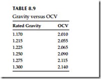
Divide that reading by number of cells in the string. The resulting per-cell value should be close to the calculated open circuit voltage (OCV) as given in Table 8.9. If the tasks above have been completed and meet the acceptance criteria, initial charging of the battery may then begin. Items that do not conform to the battery manufacturer or
IEEE standards must be noted on the inspection report and corrected.
Corrective action should be taken as soon as possible. The amount of time a battery requires to reach a fully charged state for testing is a function of several conditions:
• Applied charging voltage
• Ambient temperature
• Battery state of charge prior to commissioning
• Physical size of the cells
The commissioning charge, also referred to as a freshening or initial charge should be determined based on the requirements and tolerances of both bat- tery and the equipment to which it is connected. Determine the required applied voltage by multiplying the number of cells by the per-cell charge recommendations in the battery manufacturer operating instructions. This value must not exceed the charging system capability.
Electrochemical pretesting
In pretest, the following tasks should always be completed prior to load testing the battery system:
1. Before load tests can take place, the battery must be fully charged and the state of charge must be verified. This cannot be overemphasized. Generally, a battery is considered to be fully charged when the voltage of lowest cell in the string stops rising over three consecutive hourly readings while on equalize charge and the lowest specific gravity measurement is within the nominal rating by ±10 (0.010) specific grav- ity points. This can be used as a guideline during charging. Refer to the battery manufacturer’s specific instructions for more detail.
2. Find the lowest cell and verify the state of charge as described above.
If the cell voltage continues to rise with the next hourly reading, continue the equalize charge until it stops rising. When that cell voltage stops rising, the battery should then be returned to normal float status.
Monitor cell temperature while on charge. Do not exceed the maximum allowable temperature or cells may be damaged.
3. IEEE 450-2002, “IEEE recommended practice for maintenance, testing, and replacement of vented lead–acid batteries for stationary applications,” states a battery should receive an equalize charge and be returned to normal float potential for no less than 3 days, but not longer than 30 days prior to testing. This 3 day period will allow time for all the hydrogen gas bubbles (formed on the plates during equalize charging) to be released from the surface of the plates. Until all the bubbles are released, the full surface area of the plates is not available for chemical interaction with the electrolyte, and the battery could appear to have diminished capacity.
4. When items 2 and 3 are satisfied, measure and record the specific gravity of each cell in the battery just prior to the load test. If the gravity readings are within the manufacturer’s recommended values, (usually ±10 points), they are considered acceptable. For specific details regarding allowable gravity values, refer to the battery man- ufacturer installation and operating instructions.
5. Measure and record the electrolyte temperature of every sixth cell, with not less than 10% of the total number of cells in the battery. Battery
performance data is referenced to 77°F (25°C). Cooler temperatures will cause diminished battery capacity. Higher temperatures will result in increased capacity, but reduce service life. Temperature considerations are a frequently overlooked when load testing the battery system.
Correcting for temperature
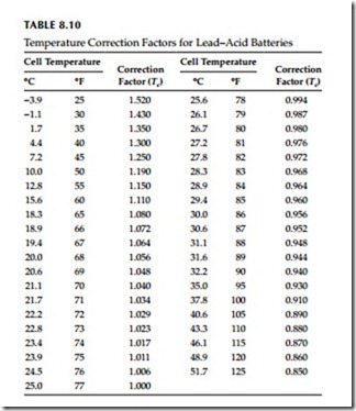
If the cell temperature is other than 77°F, some amount of compensation should be factored into the load test procedure. Unless the purchase specification called for a different operating temperature, the UPS battery was sized by the manufacturer for operation at 77°F. Therefore, battery performance will be diminished at cooler temperatures and artificially increased at higher temperatures. The simplest way to compensate for temperature is to increase or decrease the kW setting of the load bank and then testing to see if the batteries meets the originally specified time duration before being fully discharged. Correction factors for cell temperature are listed in Table 8.10.
To illustrate their use, let us take a sample UPS system rated at 750 kVA and 600 kW (rated kW), and assume the cell electrolyte temperature was measured at 67°F. Table 8.10 shows a temperature correction factor (Tc) of 1.064. Load bank setting (AC kW) can be expressed by the formula:
The original 77°F AC kW would have been 600 kW. The corrected load bank setting indicates a difference of 36 kW (6% of rated capacity). Had the battery been tested at the full 600 kW load, the battery would have lasted less than the time specified, i.e., it would have reached its discharged state before its specified time.
Maintenance and Testing
Refer to Section 7.8 on routine maintenance and testing of switchgear batteries since there are many similarities that are common to the UPS battery systems. The battery tests listed in Section 7.8 are applicable to the UPS batteries.
Summary
Many tests are involved when commissioning and maintaining an UPS system. Many parameters (three-phase voltage and current, power, power factor, harmonics, and transients) must be logged simultaneously over 8–24 h and documented in report format. Use a power quality analyzer with data logging and reporting capabilities, such as the Fluke 435 or an equal to make the required tests.
Also, it is critical to ensure battery system integrity before it is load tested. It must be fully charged, properly installed and its condition verified in order to minimize the likelihood of retests and equipment damage. When com- pared with the cost of downtime, delays, retests, and hardware failures, the cost of battery inspection is a bargain, well worth the expense and time added to a project. The above installation and maintenance guide is based on vented lead–acid batteries; however, many facilities may have VRLA batteries for their UPS installations. Many of the checklist items listed for the vented lead– acid batteries also apply to the VRLA batteries. It is recommended that the IEEE standards on the VRLA batteries be consulted for installation and maintenance. These standards are
1. IEEE 1187-2002, “IEEE recommended practice for installation design and installation of valve regulated lead–acid batteries for stationary applications.”
2. IEEE 1189-2007, “IEEE recommended practice for maintenance, testing, and replacement of valve regulated lead–acid batteries for stationary applications.”
3. IEEE 1189-2007, “IEEE guide for selection of valve regulated lead– acid batteries for stationary applications.”


