Principles of operation
No-load operation
The basic operation of all these generator types can be explained using two simple rules, the first for magnetic circuits and the second for the voltage induced in a conductor when subjected to a varying magnetic field.
The means of producing a magnetic field using a current in an electric circuit have been explained in section 2.2.3, and eqns 2.13 and 2.18 have shown that the flux Φ in a magnetic circuit which has a reluctance Rm is the result of a magneto-motive force (mmf ) Fm, which itself is the result of a current I flowing in a coil of N turns.
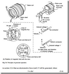
The main magnetic and electrical parts of a salient-pole generator are shown in Fig. 5.4. In Fig. 5.4(a), dc current is supplied to the rotor coils through brushes and sliprings. The product of the rotor or field current I and the coil turns N results in mmf Fm as in eqn 5.2, and this acts on the reluctance of the magnetic circuit to produce a magnetic flux, the path of which is shown by the broken lines in Fig. 5.4(b). As the rotor turns, the flux pattern created by the mmf Fm turns with it; this is illustrated by the second plot of magnetic flux in Fig. 5.4(b). In section 2.2.3 it has also been explained that when a magnetic flux Φ passes through a magnetic circuit with a cross section A, the resulting flux density B is given by
Figure 5.4(a) also shows a stator with a single coil with an axial length l. As the rotor turns, its magnetic flux crosses this stator coil with a velocity v, it has been explained
The direction of the voltage is given by Fleming’s right-hand rule, as shown in Fig. 2.6.
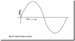
Figure 5.4(b) shows that as the magnetic field rotates, the flux density at the stator coil changes. When the pole face is next to the coil, the air gap flux density B is at its highest, and B falls to zero when the pole is 90° away from the coil. The induced emf or voltage V therefore varies with time (Fig. 5.5) in the same pattern as the flux density varies around the rotor periphery. The waveform is repeated for each revolution of the rotor; if the rotor speed is 3000 rpm (or 50 rev/s) then the voltage will pass through 50 cycles/second (or 50 Hz). This is the way in which the frequency of the electricity supply from the generator is established. The case shown in Fig. 5.4 is a 2-pole rotor, but if a 4-pole rotor were run at 1500 rpm, although the speed is lower, the number of voltage alternations within a revolution is doubled, and a frequency of 50 Hz would also result. The general rule relating the synchronous speed ns (rpm), number of poles p and the generated frequency f (Hz) is given by
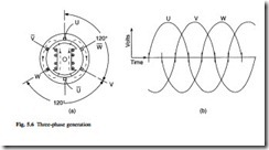
The simple voltage output shown in Fig. 5.5 could be delivered to the point of use (the ‘load’) with a pair of wires as a single-phase supply. If more coils are added to the stator as shown in Fig. 5.4(a) and if these are equally spaced, then a three-phase out- put as shown in Fig. 5.6 can be generated. The three phases are conventionally labelled ‘U’, ‘V’ and ‘W’. The positive voltage peaks occur equally spaced, one-third of a cycle apart from each other. The nature of single-phase and three-phase circuits has been explained in Chapter 2. The three coils either supply three separate loads, as shown in Fig. 5.7(a) for three electric heating elements, or more usually they are arranged in either ‘star’ or ‘delta’ arrangement in a conventional three-phase circuit (Fig. 5.7(b)).
In a practical generator the stator windings are embedded in slots, the induced voltage remaining the same as if the winding is in the gap as shown in Fig. 5.4(b). Also, in a practical machine there will be more than the six slots shown in Fig. 5.6(a). This is arranged by splitting the simple coils shown into several subcoils which occupy
separate slots, each phase still being connected together to form a continuous winding. Figures 5.1 and 5.2 show the resulting complexity in a complete stator winding.
The effect of load
In the circuits shown in Fig. 5.7 currents flow in each phase, and these currents will have a waveform similar to the voltage waveform shown in Fig. 5.6(b). The concept of a phase shift between voltage and current in ac circuits which contain inductance or capacitance has been explained in section 2.3.2. If an inductive or capacitive load is connected, then the current waveforms will respectively ‘lag’ or ‘lead’ the voltage waveforms by 90°. For the inductive load case shown in Fig. 5.6(a), the current in the U phase will be zero, but current will be flowing in V and W phases. It can be seen that the lines of magnetic flux now enclose not only the rotor excitation current, but also the stator currents in the V and W phases. Equations 5.1 and 5.2 show that the flux is the result of the mmf acting on a magnetic circuit, but it can now be seen that the mmf is a combination of the ampere-turns from the rotor and the stator winding. If Ir, Is, Nr, and Ns are the currents and turns in the stator and rotor windings respectively, then eqns 5.1 and 5.2 combine to give
In Fig. 5.6 a cross is used to indicate a current flow into the page, and a dot shows cur- rent flowing out of the page. It is seen that the stator currents oppose the field current in the rotor and their effect is to reduce the flux, with a corresponding reduction in the generated voltage. This demagnetizing effect is called ‘armature reaction’; it is the way in which Lenz’s Law (section 2.2.4) operates in a generator.
The underlined currents in eqn 5.6 indicate that these are vectors and a vector addition is necessary. The armature reaction effect therefore depends on the extent to which the stator currents lag or lead the voltages (often called the ‘phase’ or ‘phase angle’). If, for example, the generator load is capacitive, the currents will lead the voltages by 90°, and they will be opposite in direction to that shown in Fig. 5.6 for an inductive load. The ampere-turns of stator and rotor windings will add in this case and the flux and the generated voltage will be higher. In the case of a resistive load, the ampere- turns of the stator will act at 90° to the rotor poles, tending to concentrate the flux towards the trailing edge of the pole and producing magnetic saturation here when large stator currents flow; this reduces the flux and the output voltage, but not so much as in the inductive load case.
The output voltage is influenced not only by armature reaction, but also by voltage drop within the stator winding. This voltage drop is partly due to the internal resistance of the winding, and partly due to flux which links the stator winding but not the rotor winding; this flux is known as ‘leakage flux’ and it appears in the stator electrical circuit as a leakage inductance, which also creates a voltage drop. The phase angle between stator currents and voltages will affect this voltage drop, producing a greater drop at lagging currents, and a negative drop (an increase) in voltage at leading currents.
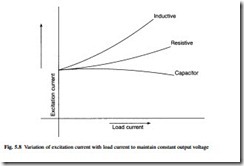
In order to maintain a constant output voltage it is therefore necessary to change the excitation current in the rotor to compensate for the load conditions. The variation in rotor current to do this is shown in Fig. 5.8. To achieve constant output voltage, an Automatic Voltage Regulator (AVR) is used on the majority of generators, except for some small self-regulating units (see section 5.4).
The effects described so far can be conveniently summarized in a phasor diagram which combines stator and rotor mmfs as well as the emf drops due to resistance and leakage reactance of the stator winding. Figure 5.9 shows the phasor diagram of a cylindrical-rotor machine. It is assumed that the machine is symmetrically loaded and the diagram is drawn for one phase.
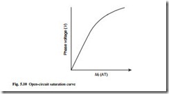
Phasor Mf represents the field-winding mmf. The output voltage that this would produce with no connected load is given by Eoc and its magnitude found by referring to the open-circuit saturation curve shown in Fig. 5.10. The reduced slope at high field currents results from saturation of the magnetic circuit. The output voltage Vs in Fig. 5.9 when under load is chosen to lie on the real axis and the output current is lagging by an angle Φ. The armature reaction mmf lags the stator current by 90° and is shown as Ma. When added to the field mmf the resultant mmf acting on the gap is shown as Mres which produces the resultant airgap flux resulting in the ‘airgap emf’ Eg. The magnitude of Eg from Mres is again found by using the saturation curve of Fig. 5.10. The output voltage is found by subtracting from Eg the resistive and leakage reactive drops IsRs and IsXs. The phasor diagram is a convenient way of calculating the steady state performance of a generator at different loads.
A similar diagram can be produced for salient-pole machines. In this case, however, the armature reaction is resolved into two components, one along the centre line of the rotor poles (the direct or d axis), and the other at an angle of 90° to this (the quadrature or q axis). These axes have different magnetic reluctance values.
These phasor diagrams are valid for steady state conditions only, and cannot be used to predict transient performance such as a sudden short circuit. A common means
of predicting transient performance is to represent the interaction of the stationary stator circuits and the rotor circuits by a matrix of mutual inductances which will be a function of rotor position. If this variation is assumed to be sinusoidal, it is possible to transform the matrix to one with constant mutual inductances by multiplying the above matrix by a transform matrix, and as a result the stator currents and voltages are trans- formed to ‘d–q values’. This simple transform, known as a d–q transform, allows the transient performance of a generator to be predicted and is particularly useful in representing fault conditions in power system networks.
Damping of transients
Transient changes in stator load result in a change of flux in the rotor pole, and if it can be arranged that this flux change induces a voltage and a flow of current in the pole face, this current will oppose the change in stator flux. To achieve this, it is normal to insert into the pole face a set of aluminium or copper ‘damper’ bars, connected at either end by a ring or end plate to form a conducting cage in the pole faces.
The damper cage has a considerable influence on the transient current flow in the stator, particularly in the case of a short circuit. In addition, if the load in the three phases is unbalanced, the induced currents in the damper cage will act to reduce distortion of the waveform and to reduce asymmetry in the output phase voltages. A single-phase generator represents a severe case of asymmetry, and this requires very careful damper cage design because of the high induced currents.
The cage also helps to damp mechanical oscillations of the rotor speed about the synchronous speed when the generator is connected in parallel with other machines. These oscillations might otherwise become unstable, leading to the poles ‘slipping’ in relation to the frequency set by other generators, and resulting in a loss of synchronism. Such a condition would be detected immediately by the generator protection circuits and the generator would then be isolated from the network.
Voltage waveform
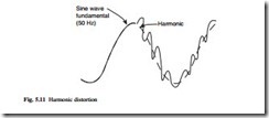
The specified voltage waveform for a generator is usually a sine wave with minimum distortion. A sine wave supply has advantages for many loads because it minimizes the losses in the equipment; this is especially the case with motors and transformers. The voltage waveform of a practical generator usually contains some distortion or harmonics, as shown in Fig. 5.11. The distorted waveform shown in Fig. 5.11(a) can be represented as a series of harmonics, consisting of the fundamental required frequency and a series of higher frequencies which are multiples of the fundamental frequency.
The harmonic distortion is calculated using Fourier analysis or other means of obtaining the spectrum of harmonics. An example of a spectrum is shown in Fig. 5.11(b). Distortion is defined by a ‘distortion factor’, where
In eqn 5.7, Vn is the magnitude of the nth harmonic, V1 being the magnitude of the fundamental one.
There are several ways in which a generator can be designed to produce minimum distortion factor.
The higher frequency ‘slot harmonics’ are due to distortions in the air gap flux den- sity wave, these being created by the stator slot openings. The distortions can be reduced by skewing the stator slots so that they are no longer parallel to the rotor shaft,
but form part of a helix. The slots are often skewed by an amount close to the pitch between one stator slot and the next.
A second step is to use more than one stator slot per pole for each phase winding; Fig. 5.12 shows a winding with three stator slots per pole for each phase. This distributes the effect of the winding better and reduces the harmonics.
Harmonics can also be reduced by ‘short-pitching’ the stator winding as shown in Fig. 5.12. Except for the smallest machines, most generators have a double-layer winding in which one side of a coil is laid into a slot above the return side of a different coil. The simplest (fully pitched) winding has all the coil sides of one phase in slots above the return sides of coils in that same phase, but by displacing one layer of the winding with respect to the other, the harmonics are reduced.
A fourth technique is to shape the face of the rotor pole so that the airgap between the rotor and stator is larger at the tips. This prevents a ‘flat-topped’ shape to the flux wave in the air gap and therefore reduces voltage distortion.
Finally, correct spacing of the damper bars in the pole face and proper choice of the arc length of the pole face reduces the high frequency harmonics which are produced by currents induced in the bars by the passage of the stator slots.
Connecting generators in parallel
Generators are frequently required to operate in parallel, either as part of a larger power system, or in a smaller isolated system. In order to connect in parallel with another generator or a larger system, the generator must produce the same magnitude and frequency of voltage as the other generators on the system. This is achieved by a synchronizing controller which controls the prime mover governor and the AVR field control. The governor must further be controlled to ensure that the phase angle of the voltages at each side of the generator circuit breaker contacts is equal. Once this con- dition is reached the contacts can be closed with a minimum of transient current. Once the generator is connected to a system, the mode of operation of the governor control must change to provide the required power, and the AVR mode must change to provide the required power factor or VArs. Where two or more generators are connected in island mode to an isolated load the governors and AVRs of all the sets must be controlled to share the power in the required ratio and also to ensure the same power factor so that circulating currents between generators are minimized.
Operating limits when in parallel with the mains
When a generator operates in parallel with a system, the power supplied by the generator is controlled by the torque control on the prime mover, for instance the rack of a diesel engine fuel injection pump. The power factor is controlled by the field or excitation current of the generator. By increasing the field current the phase angle of the stator current progressively lags that of the terminal voltage, and conversely a reduction in field current results in the stator current phase angle leading that of the terminal voltage. The power supplied by the generator will remain constant during this process if the prime mover torque is kept constant. The operator or automatic controller must be aware of the limits of the generator otherwise excessive current may occur in the field or stator windings. To this end, an operating chart is often provided by the manufacturer (sometimes referred to as the capability chart). An example is given in Fig. 5.13.
The vertical axis represents output power and the horizontal axis represents output kVAr. The output voltage is shown as OV and the output current is represented by OB, shown here lagging the voltage by φ. The field current is represented by AB. The output power is given by OD (or VI cos φ), and the output VAr is represented by OG (VI sin φ). The limits for generator operation are represented by the shaded area, where:
● BH represents the field current temperature limit
● KB represents the power limit of the prime mover
● KJ represents the practical limit of stability. Reducing field current reduces the peak torque capability of the generator, and the rotor load angle moves progressively towards the peak output angle. Any fluctuations in voltage or load can then lead to pole slipping. Automatic relay protection of generators will produce an alarm if the generator operation comes outside this area.

