Construction
Stator
The stator core is constructed from a stack of thin steel sheets or laminations which are stamped to shape and insulated electrically from each other, either by a thin coating or by an oxide layer which is produced during heat treatment. The steel used has a low silicon content as described in Chapter 3; this increases the resistivity of the steel and therefore reduces the losses due to eddy currents. The steel is carefully processed in order to minimize the hysteresis losses because the whole stator core is subjected to alternating magnetic flux. In large turbogenerators the core is built up in segments and grain-oriented steel is used to reduce the losses further.
The stator windings are located in axial slots in the stator core which are formed by the shape of the laminations. Except in high-voltage machines, the individual coils of the winding are wound with copper wire covered with a layer of polyester/polyamide enamel which is about 0.05 mm thick. The slots are lined with a tough insulating sheet, usually about 0.25–0.5 mm thick; a popular material is a laminate of Mylar and Nomex. The coils are impregnated when in place with a resin to give the winding mechanical strength as well as to improve the heat transfer from the copper to the cooling air. Windings operating at different voltages, such as the three phases, have a further sheet of insulating material separating them in the end-winding region. A general guide to the insulation materials and processes in use is given in section 3.3.
The mounting of the stator core in its frame differs according to the size of the machine, but for a majority of medium-sized generators, the arrangement is as shown in Fig. 5.18. At either end of the frame are bearing housings which locate the rotor shaft. These housings or end-bells are cast in smaller and medium size machines, and fabricated in larger sizes. The generator is often mounted directly onto the engine, and in this case it is usual to eliminate the drive-end bearing, using the rear bearing of the engine to locate the generator shaft.
Rotor
It has already been noted that the construction of a turbogenerator is very specialized and the rotor for these machines are not dealt with here. However, even within the class of salient-pole generators, quite different forms of rotor construction are used, depending upon the size.
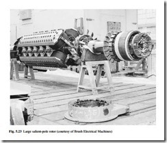
Generators rated up to about 500 kW use rotor laminations which are stamped in one piece. In larger machines the poles are made separately from stacks of laminations, and each pole is keyed using a dovetail arrangement onto a spider which is mounted on the rotor shaft. In large high-speed machines the poles can be made from solid steel for extra strength and to reduce mechanical distortion; these solid poles are screwed to the shaft, as shown in the large 4-pole machine in Fig. 5.23.
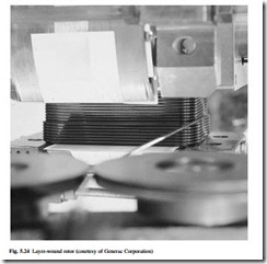
The nature of the rotor coils also depends upon the size of the machine. Because the ratio of surface area to volume is larger in the coils of small generators, these are
easier to cool. Generators rated above about 25 kW therefore use a ‘layer-wound’ coil in which each layer of the coil fits exactly into the grooves formed by the layer below; this is illustrated in Fig. 5.24. Rectangular cross section wire can be used to minimize the coil cross section. The simplest and cheapest way to make the coils, often used in smaller machines, is to wind them in a semi-random way as shown in Fig. 5.25. In either case, the coils are impregnated after winding like the stator windings to give extra mechanical strength and to improve the heat transfer by removing air voids within the coil.
The coils are under considerable centrifugal stress when the rotor turns at full speed, and they are usually restrained at both ends of the pole by bars, and by wedges in the interpole spaces, as shown in Fig. 5.23.
Cooling
Adequate cooling is a vital part of the design and performance of a generator. Forced cooling is needed because of the high loss densities that are necessary to make economic use of the magnetic and electrical materials in the generator.
The most critical areas in the machine are the windings, and particularly the rotor winding. It is explained in section 3.3 that the life expectancy of an insulation system decreases rapidly if its operating temperature exceeds recommended temperatures. It is crucial for reliability therefore that the cooling system is designed to maintain the winding temperatures within these recommended limits. As shown in Table 3.4, insulation materials and systems are defined by a series of letters according to their temperature capability. As improved insulation with higher temperature capability has become available, this has been adopted in generator windings and so the usual class of insulation has progressed from class A (40–50 years ago) through class E and class B to class F and class H, the latter two being the systems generally in use at present. Class H materials are available and proven, and this system is becoming increasingly accepted. An important part of the generator testing process is to ensure that the cool- ing system maintains the winding temperature within specified limits, and this is explained later in section 5.8.
In turbogenerators it has already been noted that very complex systems using hydrogen and de-ionized water within the stator coils are used. The cooling of small and medium-sized machines is achieved by a flow of air driven around the machine by a rotor-mounted fan. A typical arrangement is shown in Fig. 5.18. In this case the cooling air is drawn in through ducts; it is then drawn through the air gap of the machine and ducts around the back of the stator core before reaching the centrifugal fan which then expels the air from the machine. There are many variations to the cooling system, particularly for larger generators. In some machines there is a closed circulated air path cooled by a secondary heat exchanger which rejects the heat to the outside atmosphere. This results in a large and often rectangular generator enclosure as shown in Fig. 5.26.


