AC System Grounding Practices
Installing an effective ground system to achieve a good earth-to-grounding-electrode interface is only half the battle for a facility designer. The second, and equally important, element of any ground system is the configuration of grounding conductors inside the building. Many different methods can be used to implement a ground system, but some conventions always should be followed to ensure a low-resistance (and low-inductance) layout that will perform as required. Proper grounding is important whether or not the facility is located in a high-RF field.
Building Codes
As outlined previously in this chapter, the primary purpose of grounding electronic hardware is to pre- vent electric shock hazard. The National Electrical Code (NEC) and local building codes are designed to provide for the safety of the workplace. Local codes always should be followed. Occasionally, code sections are open to some interpretation. When in doubt, consult a field inspector. Codes constantly are being changed or expanded because new situations arise that were not anticipated when the codes were written. Sometimes, an interpretation will depend upon whether the governing safety standard applies to building wiring or to a factory-assembled product to be installed in a building. Underwriters Laboratories (UL) and other qualified testing organizations examine products at the request and expense of man- ufacturers or purchasers, and list products if the examination reveals that the device or system presents no significant safety hazard when installed and used properly.
Municipal and county safety inspectors generally accept UL and other qualified testing laboratory certification listings as evidence that a product is safe to install. Without a listing, the end user might not be able to obtain the necessary wiring permits and inspection sign-off. On-site wiring must conform with local wiring codes. Most codes are based on the NEC. Electrical codes specify wiring materials, wiring devices, circuit protection, and wiring methods.
Single-Point Ground
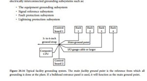
Single-point grounding is the basis of any properly designed facility ground network. Fault currents and noise should have only one path to the facility ground. Single-point grounds can be described as star sys- tems in which radial elements circle out from a central hub. A star system is illustrated in Figure 20.16. Note that all equipment grounds are connected to a main ground point, which is then tied to the facility ground system. Multiple ground systems of this type can be cascaded as needed to form a star-of-stars facility ground system. The key element in a single-point ground is that each piece of equipment has one ground reference. Fault energy and noise then are efficiently drained to the outside earth ground system. The single-point ground is basically an extension of the bulkhead panel discussed previously.
Isolated Grounding
Isolated grounding schemes, where the signal reference plane is isolated from equipment ground but connected to an isolated electrode in the earth, do not work, are unsafe, and violate the NEC [2]. It is thought by some people that the isolated earth connection is clean because there is no connection between it and the dirty system ground connection at the service entrance. The clean, isolated earth connection is also viewed (incorrectly) as a point where noise currents can flow into the earth and be dissipated. Kirchoff ‘s current law teaches that any current flowing into the isolated ground must return to the source through another earth connection. Current cannot be dissipated. It must always return to its source. Even lightning current is not dissipated into the earth. It must have a return path (i.e., the electro- static and electromagnetic fields that created the charge buildup and the lightning strike in the first place).
Consider what might happen if such a system were subjected to a lightning strike. Assume that a transient current of 2000 A flows into the earth and through an earth resistance of 5 Ω between the sys- tem ground electrode and the isolated electrode. A more realistic resistance might be even higher, per- haps 25 Ω; 2000 A flowing through 5 Ω results in a voltage drop or transient potential of 10,000 V between the two electrodes. Because this potential is impressed between the equipment frame (system ground electrode) and the signal reference plane (isolated electrode), it could result in equipment dam- age and personnel hazard. Dangerous potential differences between grounding subsystems can be reduced by bonding together all earth electrodes at a facility.
A facility ground system, then, can be defined as an electrically interconnected system of multiple conducting paths to the earth electrode or system of electrodes. The facility grounding system includes all electrically interconnected grounding subsystems such as:
Isolated ground (IG) receptacles, which are a version of single-point grounding, are permitted by the NEC. Proper application of IG receptacles is very important. They must be used with an insulated equipment grounding conductor, not a bare conductor. Also, only metallic conduit should be used.
Separately Derived Systems
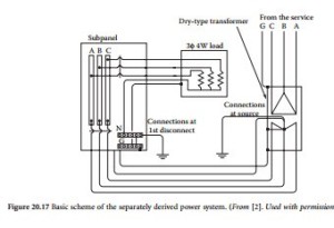
A separately derived system is a premises wiring system whose power is derived from generator, trans- former, or converter windings and that has no direct electrical connection, including a solidly connected grounded circuit conductor, to supply conductors originating in another system [3]. Solidly grounded, wye-connected, isolation transformers used to supply power to computer room equipment are examples of separately derived systems [2]. Figure 20.17 illustrates the bonding and grounding requirements of separately derived systems. NEC 250-26 permits the bonding and grounding connections to be made at the source of the separately derived system or at the first disconnecting means. Other examples of sepa- rately derived systems include generators and UPS systems. Note that all earth electrodes are bonded together via the equipment grounding conductor system. This is consistent with the recommendations listed in NEC 250-86.
Grounding Terminology
• Grounded conductor. A system or circuit conductor that is intentionally grounded [3].
• Equipment grounding conductor. The conductor used to connect the non-current-carrying metal parts of equipment, raceways, and other enclosures to the system grounded conductor, the ground- ing electrode conductor, or both, at the service equipment or at the source of a separately derived system [3].
• Main bonding jumper. The connection between the grounded circuit conductor and the equipment grounding conductor at the service [3].
• Grounding electrode conductor. The conductor used to connect the grounding electrode to the equipment grounding conductor, to the grounded conductor, or to both, of the circuit at the service equipment or at the source of a separately derived system [3].
• Service. The conductors and equipment for delivering energy from the electricity supply system to the wiring system of the premises served [3].
• Service conductors. The supply conductors that extend from the street main or from transformers to the service equipment of the premises supplied [3].
• Service equipment. The necessary equipment, usually consisting of a circuit breaker or switch and fuses, and their accessories, located near the point of entrance of supply conductors to a building or other structure, or an otherwise defined area, and intended to constitute the main control and means of cutoff of the supply [3].
• Equipotential plane. A mass of conducting material that offers a negligible impedance to current flow, thus producing zero volts (equipotential) between points on the plane.
• Floating signal grounding. A nongrounding system in which all electronic signal references are isolated from ground.
• Single-point grounding. A grounding system in which all electronic signal references are bonded together and grounded at a single point.
• Multipoint grounding. A grounding system in which all electronic signal references are grounded at multiple points.
Facility Ground System
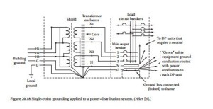
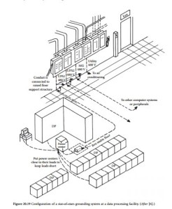
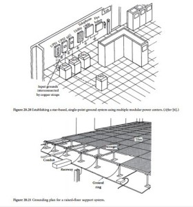
Figure 20.18 illustrates a star grounding system as applied to an ac power-distribution transformer and circuit-breaker panel. Note that a central ground point is established for each section of the system: one in the transformer vault and one in the circuit-breaker box. The breaker ground ties to the transformer vault ground, which is connected to the building ground system. Figure 20.19 shows single-point grounding applied to a data processing center. Note how individual equipment groups are formed into a star grounding system, and how different groups are formed into a star-of-stars configuration. A similar approach can be taken for a data processing center using multiple modular power center (MPC) units, as shown in Figure 20.20. The terminal mounting wall is the reference ground point for the room.
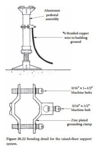
Grounding extends to all conductive elements of the data processing center. As illustrated in Figure 20.21, the raised-floor supports are integrated into the ground system, in addition to the metal work of the building. The flooring is bonded to form a mesh grounding plane that is tied to the central ground reference point of the room. This is another natural extension of the bulkhead concept discussed previously. Figure 20.22 shows connection detail for the raised-floor supports. Make sure to use a flooring sys- tem that can be bolted together to form secure electrical — as well as mechanical — connections.
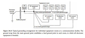
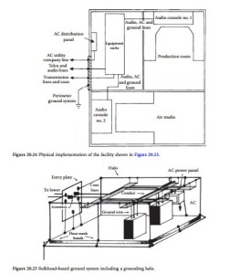
Figure 20.23 shows the recommended grounding arrangement for a typical communications facility. The building ground system is constructed using heavy-gauge copper wire (no. 4 or larger) if the studio is not located in an RF field, or a wide copper strap (3-in. minimum) if the facility is located near an RF energy source. Figure 20.24 gives a functional view of the plan shown in Figure 20.23. Note the bulkhead approach.
Run the strap or cable from the perimeter ground to the main facility ground point. Branch out from the main ground point to each major piece of equipment and to the various equipment rooms. Establish a local ground point in each room or group of racks. Use a separate ground cable for each piece of equipment (no. 12 gauge or larger). Figure 20.25 shows the grounding plan for a facility incorporating
a grounding halo. Equipment grounding is handled by separate conductors tied to the bulkhead panel (entry plate). A halo ground is constructed around the perimeter of the room. Cable trays are tied into the halo. All electronic equipment is grounded to the bulkhead to prevent ground-loop paths. In this application, the halo serves essentially the same function as the raised-floor ground plane in the data processing center.
The ac line ground connection for individual pieces of equipment often presents a built-in problem for the system designer. If the equipment is grounded through the chassis to the equipment-room ground point, a ground loop can be created through the green-wire ground connection when the equipment is plugged in. The solution to this problem involves careful design and installation of the ac power- distribution system to minimize ground-loop currents, while at the same time providing the required protection against ground faults. Some equipment manufacturers provide a convenient solution to the ground-loop problem by isolating the signal ground from the ac and chassis ground. This feature offers the user the best of both worlds: the ability to create a signal ground system and ac ground system that are essentially free of interaction and ground loops. Do not confuse this isolated signal ground with the isolated ground system described previously. In this context, isolated refers only to the equipment input/ output (signal) connections, not the equipment chassis; there is still only one integrated ground system for the facility, and all equipment is tied to it.
of a ground system must be considered as an integrated package. Proper procedures must be used at all points in the system. It takes only one improperly connected piece of equipment to upset an otherwise perfect ground system. The problems generated by a single grounding error can vary from trivial to significant, depending upon where in the system the error exists. This consideration leads, naturally, to the concept of ground-system maintenance for a facility. Check the ground network from time to time to ensure that no faults or errors have occurred. Anytime new equipment is installed, or old equipment is removed from service, careful attention must be given to the possible effects that such work will have on the ground system.
Grounding Conductor Size
The NEC and local electrical codes specify the minimum wire size for grounding conductors. The size varies, depending upon the rating of the current-carrying conductors. Code typi- cally permits a smaller ground conductor than hot conductors. It is recommended, however,
involved in the larger ground wire often is offset by the use of a single size of cable. Furthermore, better control over noise and fault currents is achieved with a larger ground wire.
It is recommended that separate insulated ground wires be used throughout the ac distribution sys- tem. Do not rely on conduit or raceways to carry the ground connection. A raceway interface that appears to be mechanically sound may not provide the necessary current-carrying capability in the event of a phase-to-ground fault. Significant damage can result if a fault occurs in the system. When the electri- cal integrity of a breaker panel, conduit run, or raceway junction is in doubt, fix it. Back up the mechanical connection with a separate ground conductor of the same size as the current-carrying conductors. Loose joints have been known to shower sprays of sparks during phase-to-ground faults, creating a fire hazard. Secure the ground cable using appropriate hardware. Clean attachment points of any paint or dirt accumulation. Properly label all cables.
Structural steel, compared with copper, is a poor conductor at any frequency. At dc, steel has a resistivity 10 times that of copper. As frequency rises, the skin effect is more pronounced because of the magnetic effects involved. A no. 6 copper wire can have less RF impedance than a 12-in. steel “I” beam. Furthermore, because of their bolted, piecemeal construction, steel racks and building members should not be depended upon alone for circuit returns.
High-Frequency Effects
A significant amount of research has been conducted into why the 60 Hz power grounding system is incapable of conducting RF signals to the common reference point, thereby equalizing existing differ- ences in potential [4]. A properly designed power grounding system is of sufficiently low impedance at 60 Hz to equalize any potential differences so that enclosures, raceways, and all grounded metal elements are at the same reference (ground) potential. However, at higher frequencies, equalization is prevented because of increased impedance.
The impedance of a conductor consists of three basic components: resistance, capacitive reactance, and inductive reactance. Although the inductance L (in Henrys) will be constant for a conductor of a given length and cross-sectional area, the inductive reactance XL will vary according to the frequency f of the applied voltage as follows:
Therefore, at 60 Hz, the inductive reactance will be 377 × L; at 30 MHz, it will be (188.5 × 10⁶) × L. It is evident, then, that at 60 Hz the equipment grounding conductor is a short circuit, but at 30 MHz, it is effectively an open circuit.
In addition to increased inductive reactance at higher frequencies, there are also stray capacitance and stray inductance between adjacent conductors or between conductors and adjacent grounded metal, as well as resonance effects. These factors combine to yield an increase in apparent conductor impedance at higher frequencies.
If conductors are connected in a mesh or grid to form a multitude of low-impedance loops in parallel, there will be little voltage difference between any two points on the grid at all frequencies from 60 Hz up to a frequency where the length of one side of the square represents about 1/10 wavelength. A grid made up of 2-ft squares (such as a raised computer-room floor) will at any point provide an effective equipotential ground reference point for signals up to perhaps 30 MHz.
Power-Center Grounding
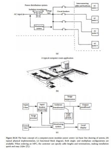
A modular power center, commonly found in computer-room installations, provides a comprehensive solution to ac power-distribution and ground-noise considerations. Such equipment is available from several manufacturers, with various options and features. A computer power-distribution center gener- ally includes an isolation transformer designed for noise suppression, distribution circuit breakers, power-supply cables, and a status-monitoring unit. The system concept is shown in Figure 20.26. Input power is fed to an isolation transformer with primary taps to match the ac voltage required at the facility. A bank of circuit breakers is included in the chassis, and individual preassembled and terminated cables supply ac power to the various loads. A status-monitoring circuit signals the operator if any condition is detected outside normal parameters.
The ground system is an important component of the MPC. A unified approach, designed to pre- vent noise or circulating currents, is taken to grounding for the entire facility. This results in a clean ground connection for all equipment on-line.
The use of a modular power center can eliminate the inconvenience associated with rigid conduit installations. Distribution systems also are expandable to meet future facility growth. If the plant ever is relocated, the power center can move with it. MPC units usually are expensive. However, considering the costs of installing circuit-breaker boxes, conduit, outlets, and other hardware on-site by a licensed electri-
cian, the power-center approach may be economically viable. The use of a power center also will make it easier to design a standby power system for the facility. Many computer-based operations do not have a standby generator on-site. Depending on the location of the facility, it might be difficult or even impossi- ble to install a generator to provide standby power in the event of a utility company outage. However, by using the power-center approach to ac distribution for computer and other critical load equipment, an uninterruptible power system can be installed easily to power only the loads that are required to keep the facility operating. With a conventional power-distribution system — where all ac power to the building, or a floor of the building, is provided by a single large circuit-breaker panel — separating the critical loads from other nonessential loads (such as office equipment, lights, and heating equipment) can be an expensive detail.
Isolation Transformers
One important aspect of an MPC is the isolation transformer. The transformer serves to:
• Attenuate transient disturbances on the ac supply lines
• Provide voltage correction through primary-side taps
• Permit the establishment of a local ground reference for the facility served
Whether or not an MPC is installed at a facility, consideration should be given to the appropriate use of an isolation transformer near a sensitive load.
The ac power supply for many buildings originates from a transformer located in a basement utility room. In large buildings, the ac power for each floor can be supplied by transformers closer to the loads they serve. Most transformers are 208 Y/ 120 V three-phase. Many fluorescent lighting circuits operate at 277 V, supplied by a 408 Y/277 V transformer. Long feeder lines to DP systems and other sensitive loads raise the possibility of voltage fluctuations based on load demand and ground- loop-induced noise.
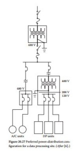
Figure 20.27 illustrates the preferred method of power distribution in a building. A separate dedicated isolation transformer is located near the DP equipment, providing good voltage regulation and permitting the establishment of an effective single- point star ground in the data processing center. Note that the power-distribution system voltage shown in the figure (480 V) is maintained until the DP step-down isolation transformer. Use of this higher voltage provides more efficient transfer of electricity throughout the plant. At 480 V, the line current is about 43% of the current in a 208 V sys- tem for the same conducted power.
There are a number of tradeoffs with regard to facility ac power-system design. An experienced, licensed electrical contractor or registered professional engineer should be consulted during the

