On-board computer
The computer that oversees engine functions goes under various names— electronic or engine control unit (ECU), power train control module (PCM), or micro- controller. We’ll follow the example of Caterpillar and Detroit Diesel and call the computer an electronic control module (ECM).
Central processing unit
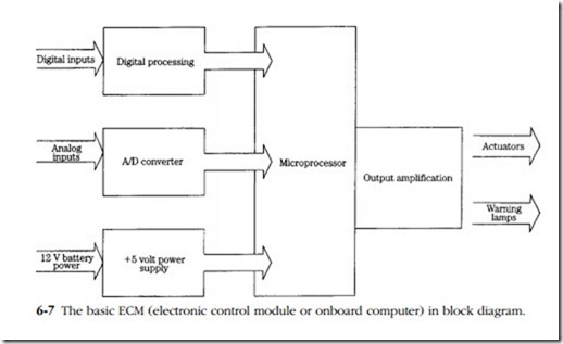
The central processing unit or microprocessor (CPU) chip contains millions of tiny transistors that integrate sensor data and operator commands to generate the out- puts necessary to control the engine (Fig. 6-7). The CPU performs arithmetic calculations, makes decisions on the basis of algebraic logic, and consults data held in memory. Data usually takes the form of maps, which plot changes in one parameter against two others. For example, injection timing is plotted against engine load and rpm. The CPU could calculate the required timing from sensor inputs, but it’s faster to look up the answer on a map.
Memory
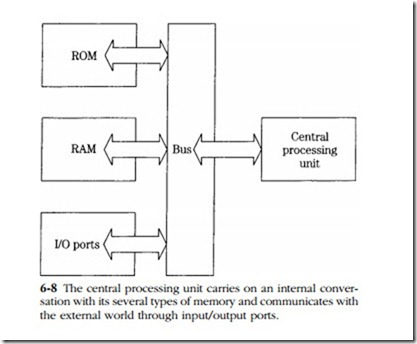
Transient data, such as ambient air temperature and fuel pressure that can be for- gotten when the engine is shut down, are stored in random access memory (RAM rep- resented diagrammatically in Fig. 6-8). Upon restarting, RAM collects new data, updated hundreds of times a second. Operating instructions, diagnostic routines, and other constants reside in read-only memory (ROM), where they remain as if chiseled in stone.
Flash memory is a semi-permanent repository that, like a Swiss bank account, requires a closely held password for access. Manufacturers use flash to adapt standard ECMs to various engine families, each of which has unique operating parameters. Factory technicians, armed with the correct password, can “reflash” this type of memory with updated programs and patches to correct the bugs that invariably appear in service. The Motorola 6800, a pioneer 8-bit microprocessor found in early Caterpillar systems and in millions of GMC automobiles, had 160 kb of flash memory and 32 kb of RAM. The 32-bit Adem 2000, now specified by Cat, has 256 kb of RAM and 1 Mb of flash. The Motorola MPC 500, currently specified by Magneti Marelli Power Trains for automotive applications, has similar capabilities.
Peripherals
In order to interact with the external world, the CPU requires peripherals, such as a converter to translate analog signals from temperature and pressure sensors into digital format. Driver circuits, often working through relays, provide the amperage for electronic injectors, fan motors, turbo wastegates, and other current-hungry actu- ators. One or more timers, controlled by oscillating crystals, give the CPU the precise time reference necessary to orchestrate injection timing and duration relative to inputs from the camshaft position sensor.
Computer capabilities evolve faster than the hardware: the MPC5500, released in 2003, can actuate electronic intake and exhaust valves, vary camshaft timing and control electro-mechanical braking, when these features become available.
Sensors
Advanced c-r systems for motor vehicles include the following sensors:
• Temperature—ambient, coolant, intake air, fuel, and exhaust (upstream and/or downstream of turbo). Most of these sensors are negative tempera- ture coefficient types, which lose internal resistance as temperature increases. Coolant and exhaust temperature sensor elements collect deposits that should be periodically removed.
• Pressure—atmospheric, fuel, turbo boost, crankcase, exhaust, and com- pressed air (for heavy trucks). Exhaust-gas pressure sensors monitor pres- sure drops across particulate traps.
• Position—rack, idle mode, variable-geometry turbocharging (VGT) control, turbo wastegate, back-pressure, and exhaust gas recirculation (EGR) valves. These sensors generally take the form of a switch or variable resistor.
• Mass air flow entering the manifold.
• Oxygen content in exhaust gas.
• Velocity—crankshaft rpm, road speed and, for some applications, turbo rpm. A coil responds to shifts in the magnetic field by generating a small signal voltage.
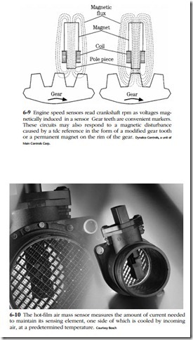
One-off EM systems, custom-built for existing installations, often retain the mechanical governor as a way to reduce costs. Production systems incorporate elec- tronic governing, whose operation is controlled by the computer in concert with a magnetic engine-speed sensor. The ECM also uses speed-sensor data to calculate injector pulse width. Figure 6-9 illustrates sensor operation, which uses gear teeth as markers. Some speed sensors pick up the rpm signal from a single gear tooth, which has a distinctive shape and magnetic signature.
In addition, a Hall-effect sensor, triggered by slit on the camshaft gear, generates a timing reference and, in some applications, reports engine speed. Failure of the camshaft position sensor shuts the engine down, often without warning. Bosch sys- tems have a fail-safe feature that enables the computer to calculate timing from the crankshaft speed sensor when the primary reference is lost. The engine will continue to run, but starting may be more difficult. For some Cat models, either sensor can stand in for the other.
As mentioned earlier, accelerator position is reported as changes in the band width (duration of voltage) generated by the throttle position sensor (TPS). These sen- sors are not without problems, and Bosch again comes to the rescue by providing a second, backup throttle position sensor.
A mass air flow (MAF) sensor measures the volume of air entering the engine as a function of its cooling effect on a heated film or a platinum wire (Fig. 6-10). Supporting electronics measure how much current is needed to maintain the film at target temperature, which is about 75° F above ambient. As engine speed and air flow increase, correspondingly more current is needed. Current draw appears as an
analog output voltage of between 0 and 5V. MAF sensors lose accuracy when contaminated and can be ruined by rough handling.
One would imagine that the computer, capable of several hundreds of thou- sands operations a second, would exert absolute control over the engine. But things get out of hand in ways the computer cannot predict. For example, fuel quality varies with each fill-up, injector nozzles wear unevenly, humid air exerts a greater cooling effect on MAF sensors than dry air. These and a hundred other variables affect combustion efficiency. The O2, or lambda, sensor closes the control loop by monitoring the level of oxygen in the exhaust gases.
Unlike other sensors, the platinum-coated zirconium-oxide O2 sensor generates its own voltage. Once it reaches operating temperature (approximately 700°C), the sensor develops nearly 0.7V in fuel-rich environments. As less fuel is burned and the oxygen content of the exhaust approaches that of the atmosphere, sensor voltage drops off to nearly zero. Signal voltage exhibits a sawtooth pattern. Normally, the computer uses this data, in conjunction with air-flow data, to deliver no more fuel than needed for combustion. Under load, the computer relaxes its standards a bit, richening the mixture for more torque. The O2 sensor then functions as a smoke limiter. The sensor also influences the amount of exhaust gas recirculated into the combustion chambers.
Inline engines have an O2 sensor threaded into the exhaust manifold at Y, where temperatures are high and exhaust gases are representative of all cylinders. V-type engines replicate the arrangement for each bank. An electrically heated four- wire (two wires to ground, one carrying signal voltage and the other battery voltage to the heater) O2 sensor will also be installed downstream of the catalytic converter. This sensor monitors converter efficiency and has no effect upon mixture strength. OBD-2 sensors are good for 100,000 miles, although response slows with age and contamination.
In event of malfunction, the EMS can disregard the O2 sensors and enter into open-loop operation. Working without the benefit of feedback, the computer adjusts fuel delivery to programmed values. Open-loop operation is, with good reason, called the “limp-home” mode.
Actuators
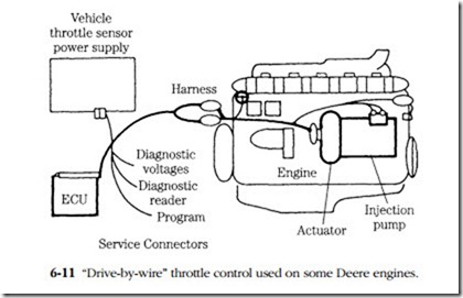
Sensors provide data to the ECM and actuators carry out the computer’s commands. The primary actuators are the electronic injectors, part and parcel of any EMS. Another almost universal type of actuator is the electronic governor. Figure 6-11 sketches the “drive-by-wire” governor used on the Deere 7L 6076 H. A switch on the electronic control module enables the operator to select any of three speed-control programs—true all-speed governing (as used in vehicles), min-max governing (for generator applications), and full-power boost. The latter option has a timer associated with it to prevent engine damage.
Other actuators control fuel pressure, turbo boost and, in some applications, exhaust back pressure.


