Ground Resistance Measurements
To maintain sufficiently low resistance values of grounding systems, their periodic testing is required. The testing involves measurement to ensure that they do not exceed design limits. The methods of measuring and testing the ground resistance and soil resistivity are as follows:
• Two-point method
• Three-point method
• Fall-of-potential method
• Ratio method
• Four-point method
• Touch potential measurements
• Clamp-on method
The measurement of ground resistances may only be accomplished with specially designed test equipment. The most common method for measuring ground resistance uses the fall-of-potential principle of alternating current (AC) of 60 Hz or some higher frequency circulating between an auxiliary electrode and the ground electrode under test; the reading will be given in ohms and represents the resistance of the ground electrode to the surround- ing earth. Also, one manufacturer has recently introduced a clamp-on ground resistance tester.
Two-Point Method
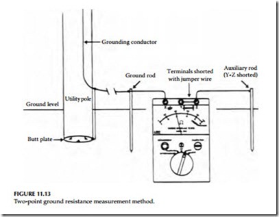
This method may be used to measure the resistance of a single driven ground rod. It uses an auxiliary ground rod whose resistance is either known or can be measured. The resistance value of the auxiliary ground rod also must be very small compared to the resistance of the driven ground rod so that the measured value can be assumed to be wholly contributed by the driven ground rod. For example, this test might be applicable in the measurement of resistance of the single driven ground rod for a residence or in congested areas where finding room to drive two auxiliary rods may be a problem.
this case, the municipal metallic water supply line can be assumed as the auxiliary ground rod whose resistance value is approximately 1 Ω or less.
This value is quite small compared to the value of a single driven ground rod, whose value is in the order of 25 Ω. The reading obtained is that of the two grounds in series. The lead resistances will also be measured and should be deducted from the final measurements. This method is usually adequate where a go, no-go type of test is required. The connections for this test are shown in Figure 11.13.
Three-Point Method
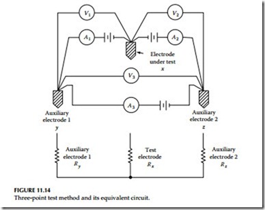
This method is similar to the two-point method except it uses two auxiliary rods. To obtain accurate values of resistance measurements, the resistance of the auxiliary electrodes should be approximately equal to or less than that of the electrode under test. The connections for the three-point method are shown in Figure 11.14.
Either AC of 60 Hz or DC may be used for making this test. The advantage of using AC is that it minimizes the effects of stray currents on measurement readings. However, if stray currents happen to be of the same frequency, error will be introduced in the readings. The use of DC for making this test will totally eliminate the AC stray currents. However, stray DC and formation of gas around the electrodes will introduce error in the readings when using DC
for this test. The effect of stray DCs can be minimized by taking readings with current in the opposite direction. The average of the two readings will give an accurate test value. Apply currents only long enough to take readings.
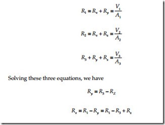
The resistance value of the test electrode can be calculated as follows. Let


