Voltage sources
Starting and charging systems employ two voltage sources. The generator is electromagnetic in nature and is the primary source. The battery, which is electro- chemical in nature, is carried primarily for starting. Also, in case of overloads, the battery can send energy into the circuit.
Generator principles
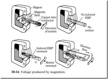
In 1831 Michael Faraday reported that he had induced electricity in a conductor by means of magnetic action. His apparatus consisted of two coils, wound over each other but not electrically connected. When he made and broke the circuit to one coil, momentary bursts of current were induced in the second. Then Faraday wound the coils over a metal bar and observed a large jump in induced voltage. Finally he reproduced the experiment with a permanent magnet. Moving a conductor across a magnetic field produced voltage. The intensity of the voltage, depended on the strength of the field, the rapidity of movement, and the angle of movement. His generator was most efficient when the conductor cut the lines of force at right angles.
The rubber band effect mentioned earlier helps one to visualize what happens when current is induced in the conductor. A secondary magnetic field is set up,
which resists the movement of the conductor through the primary field. The greater the amount of induced current, the greater the resistance, and the more power required to overcome it.
Alternator
Figure 10-16 illustrates Faraday’s apparatus. Note that there must be relative movement between the magnetic field and conductor. Either can be fixed as long as one can move. Note also that the direction of current is determined by the direction of movement. Of course, this shuttle generator is hardly efficient; the magnet or con- ductor must be accelerated, stopped, and reversed during each cycle.
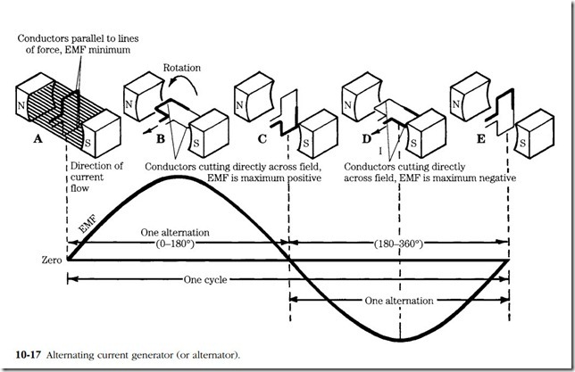
The next step was to convert Faraday’s laboratory model to rotary motion (Fig. 10-17). The output alternates with the position of the armature relative to the fixed magnets. In Fig. 10-17A the windings are parallel to the lines of force and the output is zero. Ninety degrees later the output reaches its highest value because the armature windings are at right angles to the field. At 180° of rotation (C) the output is again zero. This position coincides with a polarity shift. For the remainder of the cycle, the movement of the windings relative to the field is reversed.
To determine the direction of current flow from a generator armature, position the left hand so that the thumb points in the direction of current movement and the forefinger points in the direction of magnetic flux (from the north to the south pole). Extend the middle finger 90° from the forefinger; it will point to the direction of cur- rent. As convoluted as the lefthand rule for generators sounds, it testifies to the fact that polarity shifts every 180° of armature rotation. This is true of all dynamos, whether the machine is DC generator or AC generator (alternator).
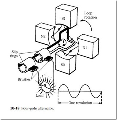
The frequency in hertz depends on the rotational speed of the armature and on the number of magnetic poles. Figure 10-18 illustrates a four-pole (two-magnet) alternator, which for a given rpm, has twice the frequency of the single-pole machine in
the previous illustration. Normally, alternators supplied for diesel engines have four magnetic poles and are designed to peak at 6000 rpm. Their frequency is given by:
where f is frequency in hertz and P is the number of poles. Thus, at 6000 rpm, a typical alternator should deliver current at a frequency of 2000 Hz.
The alternators depicted in Figs. 10-17 and 10-18 are simplifications. Actual alternators differ from these drawings in two important ways. First, the fields are not fixed, but rotate as part of an assembly called the rotor. Secondly, the fields are not permanent magnets; instead they are electromagnets whose strength is controlled by the voltage regulator. Electrical connection to the rotor is made by a pair of brushes and slip rings.
DC generator
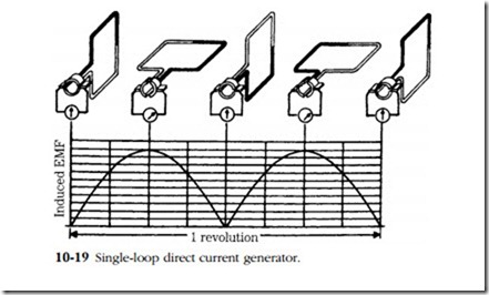
Direct-current (DC) generators develop an alternating current (AC) that is mechan- ically rectified by the commutator—brush assembly. The commutator is a split copper ring with the segments insulated from each other. The brushes are carbon bars that are spring-loaded to bear against the commutator. The output is pulsating direct current, as shown in Fig. 10-19. The pulse frequency depends on the number of armature loops,
field poles, and rpm. A typical generator has 24–28 armature loops and 4 poles. The fields are electromagnets and are energized by 8–12% of the generator output cur- rent. The exact amount of current detailed for this excitation depends on the regulator, which in turn, responds to the load and state of charge of the generator. A few surviving generators achieve output regulation by means of a third brush.
Third-brush generator
The third brush is connected to the field coils as shown in Fig. 10-20. At low rotational speeds the magnetic lines of force bisect the armature in a uniform manner. But as speed and output increase, the field distorts. The armature generates its own field, because a magnetic field is created at right angles to a conductor when current flows through it. The resulting field distortion, sometimes called magnetic whirl, places the loops feeding the third brush in an area of relative magnetic weakness. Consequently, less current is generated in these loops, and the output to the fields is lessened. The fields become correspondingly weak, and the total generator output as defined by the negative and positive brushes remains stable or declines.
The output depends on the position of the third brush, which can be moved in or out of the distorted field to adjust output for anticipated loads. Moving the brush in the direction of armature rotation increases the output; moving it against the direction of rotation reduces the output. When operated independently from the external circuit, the brushes must be grounded to protect the windings. Many of these generators have a fuse in series with the fields.


