dc motors
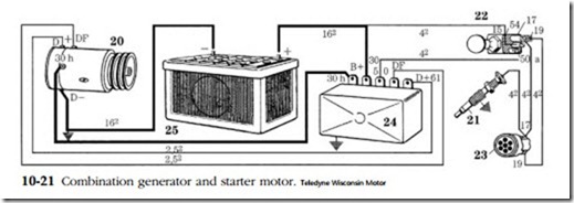
One of the peculiarities of a direct current generator is that it will ‘motor’ if the brushes are connected to a voltage source. In like manner a direct current motor will “gen” if the armature is rotated by some mechanical means. Some manufacturers of
small-engine accessories have taken advantage of this phenomenon to combine both functions in a single housing. One such system is the Dynastart system employed on many single-cylinder Hatz engines (shown schematically in Fig. 10-21).
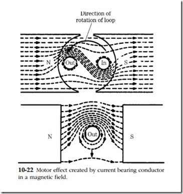
Figure 10-22 illustrates the motor effect. In the top sketch the conductor is assumed to carry an electric current toward you. The magnetic flux around it travels in a clockwise direction. Magnetic lines of force above the conductor are distorted and stretched. Because the lines of force have a strong elastic tendency to shorten, they push against the conductor. Placing a loop of wire in the field (bottom sketch)
instead of a single conductor doubles the motor effect. Current goes in the right half of the loop and leaves at the left. The interaction of the fields causes the loop (or, collectively, the armature) to turn counterclockwise. Reversing the direction of the current would cause torque to be developed in a clockwise direction.
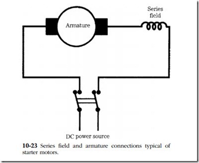
Starter motors are normally wired with the field coils in series with the armature (Fig. 10-23). Any additional load added to a series motor will cause more current in the armature and correspondingly more torque. Because this increased current must pass through the series field, there will be a greater flux. Speed changes rapidly with load. When the rotational speed is low, the motor produces its maximum torque. A starter might draw 300A during cranking, more than twice that figure at stall.


