Motors and Generators
The electrical insulation system is the most prominent part of motors and generators that needs periodic maintenance and testing. The insulation system of machines is subjected to varying degrees of mechanical, thermal, and electrical stresses. The reliability of a machine depends upon the integ- rity of its insulation system. Therefore, a preventive maintenance program should include an effective testing program, along with visual inspection and routine maintenance, to evaluate the insulating system.
The insulating parts found in motors and generators consist of stator wind- ings, field windings, winding support, collector lead and ring, stator core, and others. The maintenance and testing program should be planned to detect and provide data on deteriorating factors to which motors and generators are subjected. The following DC tests can be conducted for the purposes of preventive maintenance to assess the condition of insulation systems of motors and generators.
Insulation Resistance Test
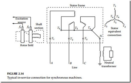
This test is conducted with voltages from 500 to 5000 V and provides information on the condition of machine insulation. A clean, dry insulation system has very low leakage as compared to a wet and contaminated insulation system. This test does not check the high-voltage strength of the insulation system, but does provide information whether the insulation system has high leakage resis- tance or not. This test is commonly made before the high-voltage test to identify insulation contamination or faults. This test can be made on all or parts of the machine circuit to ground. The following procedures are given for making this test on field winding, stator windings, and individual stator windings. Typical synchronous motor or generator connections are shown in Figure 2.14.
Field-Winding Test Procedures
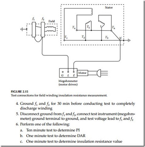
The test connection is shown in Figure 2.15 and the procedures are as follows:
1. Lift brushes on the rotor
2. Disconnect neutral terminal from neutral device or ground
3. Ground all stator terminals, stator frames, and rotor shaft
4. Ground f1 and f2 for 30 min before conducting test to completely discharge winding
5. Disconnect ground from f1 and f2, connect test instrument (megohm- meter) ground terminal to ground, and test voltage lead to f1 and f2
6. Perform one of the following:
a. Ten minute test to determine PI
b. One minute test to determine DAR
c. One minute test to determine insulation resistance value
Overall Stator (Armature Windings) Test
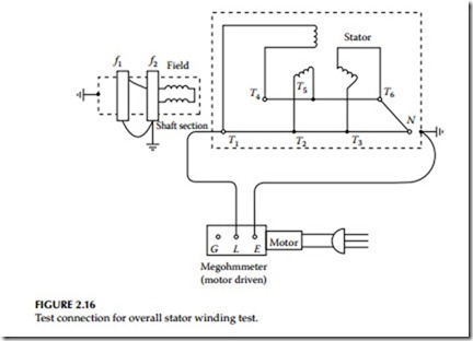
The following procedures are given for conducting this test, and the connec- tion diagram is shown in Figure 2.16.
1. Check that stator frame and rotor shafts are grounded
2. Ground rotor terminals f1 and f2
3. Connect ground terminal of instrument to ground and connect test voltage lead to all motor terminals that are connected together
4. Remove ground connection from stator winding
5. Perform the following:
a. Ten minute test, that is, PI test
b. One minute test, that is, DAR test
c. One minute test, that is, insulation resistance value
Overall System Test for the Motor or Generator
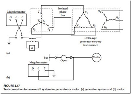
The overall system test includes generator neutral, transformer, all stator windings, isolated phase bus, and low side windings of generator step-up transformer. This test is performed as a screening test after an abnormal occurrence on the machine. If the reading is satisfactory, no further tests are made. If the reading is questionable or lower, the machine terminals are disconnected and further isolation performed to locate the source of the trou- ble. Similarly, it may be desirable to test a motor including its cables to pre- vent disconnection of motor terminals unnecessarily. The connection diagrams are shown in Figure 2.17a and b for generator system and a motor, respectively.
Individual Stator Winding Test
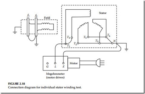
The following procedures are given for conducting this test, and the test con- nection diagram is shown in Figure 2.18.
• Ground stator terminals for 30 min
• Disconnect all stator terminals T1 through T6 and leave neutral ter- minal disconnected
• Test T1–T4 winding with T2–T5, T3–T6, and rotor grounded
• Test T2–T5 winding with T3–T6, T1–T4, and rotor grounded
• Test T3–T6 winding with T1–T4, T2–T5, and rotor grounded
The connections for the four insulation resistance measurement tests are summarized in Table 2.7.
The IEEE standard 43-2000, “Recommended Practices for Testing Insulation Resistance of Rotating Machinery,” provides information on making and
interpreting insulation resistance measurements for rotating machinery. It reviews the factors that affect or change insulation resistance characteris- tics, outlines and recommends uniform methods for making tests, and pres- ents formulas for the calculation of approximate minimum insulation resistance values for various types of AC and DC rotating machinery. The guide states:
The recommended minimum insulation resistance Rm for AC and DC machine armature windings and for field windings of AC and DC machines can be determined by
Rm = kV + 1
where
Rm = recommended minimum insulation resistance in megohms at 40°C of the entire machine winding
kV = rated machine terminal to terminal potential, in kilovolts
In applications where the machine is vital, it has been considered good practice to initiate reconditioning should the insulation resistance, having been well above the minimum value, drop appreciably to near that level.
The PI value of 2 or more is acceptable for insulating systems such as varnish-impregnated windings and asphalt windings, whereas thermoplastic insulation systems have a higher value than 2. A PI value of less than 1.0
indicates deterioration of the windings, which should be investigated. A very high PI value (above 5) indicates dried out, brittle windings such as is the case in very old machines.
DC Overpotential Test
The DC overpotential test is conducted on motors and generators to assess the insulation dielectric strength. This test can be made during routine main- tenance or after repairs have been made on the machine. Either all or parts of the machine can be tested to ground to ensure that the insulation system has sufficiently high dielectric strength for safe operation.
As a general rule, the AC voltage used for the factory proof testing of the machine windings of motors or generators is based upon the rated operating voltages of the machine. A commonly used rule for establishing factory test values for stator windings is two times rated voltage (E) plus 1000 V. For DC field winding it is 10 times the excitation voltage. To convert these value to DC overpotential test values, the multiplying factor is 1.7. The recommended DC acceptance test voltage is 75% of the equipment AC voltage used for the factory proof test, whereas the recommended DC maintenance test voltage is 65% of the factory proof test value. These values can be represented by the following equations:
The values mentioned may be varied depending upon the type and size of the machine. The standard duration of the DC overpotential test is usually 1–5 min for most electrical machines but may be varied depending upon the type and size. The reader is urged to consult IEEE standard 95-2007, Guide for Insulation Testing of AC Electric Machinery (2300 V and above) with High Direct Voltage, for further information on this subject. To obtain mean- ingful results, the DC maintenance test voltage should not be below 50% of the equipment AC factory test value.
Voltage versus Leakage Current Test (Step-Voltage Test)
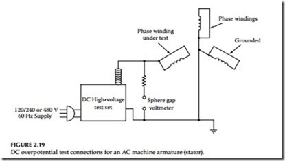
The DC overpotential test is a controlled test; that is, the increase in applied voltage is controlled by monitoring the leakage current to identify any impending failures of the winding insulation with the intention of stopping the test before the breakdown occurs. This test is commonly known as the
step-voltage test, and the test connection diagram is shown in Figure 2.19. This test procedure may be described as follows:
• First voltage step is usually one-third of the calculated test voltage, which is applied to the machine. Readings are taken at 1 min inter- vals up to a maximum of 10 min.
• Next step is to increase the test voltage in about-equal 1000 V steps and record the leakage current value for each step. Allow sufficient time between each step for leakage current to become stable.
• At each step, plot the values of leakage current on the vertical axis versus the applied test voltage on the horizontal axis. For a good insu- lation system, the curve generated by the readings will be smooth with rising slope. Any sudden changes in curve characteristics are indications of impending winding failure.
• Take steps to eliminate the possibility of excessive leakage due to ionization in order to measure the true leakage current.
Leakage Current versus Time Test
This test can be made in lieu of the voltage versus leakage current test. In this test, the point is to separate the absorption current from the total leakage current. In this test, reasonable time is allowed during each step of applied test voltage to allow the absorption current to disappear before read- ings are taken. To completely eliminate the absorption current, many hours of test time will be necessary. Therefore, a reasonable time interval is taken to be a 10 min waiting period during each step of applied voltage. The IEEE standard 95 describes this test in its appendix; which may be summarized as follows:
• Apply an initial voltage of about 30% on the machine winding and hold for 10 min. The readings are taken at regular intervals and are plotted on a log–log graph, with leakage current on the vertical axis and time on the horizontal axis.
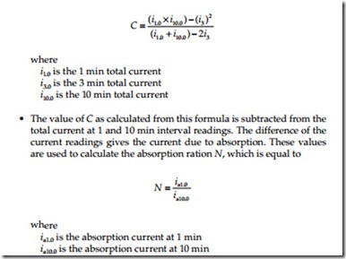
• A curve is generated by the points plotted on the graph. This curve is used to calculate the conduction component (leakage current) of measured current. The total current readings at time intervals of, say, 1, 3, and 10 min are used and substituted into the following for- mula for calculation of the conduction component (C):
• The absorption ratio N is then used to select the time intervals from a precalculated schedule, as shown in IEEE standard 95.
• The test now may be carried out for the remaining steps of test volt- age using the precalculated values of time steps. The readings of leakage current versus voltage are taken at the end of each step.
• A new curve may be generated by plotting the leakage current on the vertical axis and voltage on the horizontal axis. The curve obtained should be a straight line with rising slope if the rate of increase of conduction current component is linear. Moisture in the insulation system will produce a continuous upward slope, whereas void ionization will exhibit minor breaks in the slope of the curve. However, a sharp break in the curve will usually indicate an impending failure.
