Classification and Approach for the Thermal Stress Analysis
However, correctly transforming the mission profile of wind power converter into the corresponding thermal stress of the power devices is not an easy task [9, 11]: For example, many factors influence on the loading of converter which should be taken into account, like the wind speed variations, grid disturbances, control strategies, converter design, etc., thus multidisciplinary approaches may be involved. Also in the case of long-term stress analysis (e.g., 1-year operation which is necessary for reliability estimation [10]), large amount of loading data at various time constants from seconds to months may be generated and difficult to handle. Therefore, it is important first to identify and distinguish the causes of thermal stresses.
Classification of Thermal Stress in Wind Power Converter
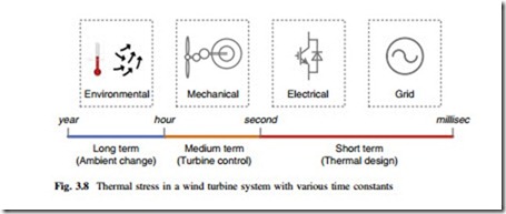
According to the time intervals, the thermal behaviors of the wind power converter can be categorized into the three types, as indicated in Fig. 3.8, in which the ranges of the dominant time constants and the corresponding main causes are defined.
Criteria and Tools for Evaluating Wind Power Converter
A. Long-Term Thermal Behavior (Days to Years)
This group of thermal behavior is mainly caused by the environmental disturbances, e.g. the variation of wind speeds or the ambient temperatures in a few months or years. The corresponding thermal stress of components will change enormously but slowly in a long term. In order to get an acceptable data size and maintain enough information for daily-based thermal behaviors, simplified models and larger sampling time may be needed for analysis.
B. Medium-Term Thermal Behavior (Seconds to Minutes)
This group thermal behavior is mainly caused by the wind speed variations and the mechanical control of wind turbines, for example, the short-term wind gust ranging from seconds to minutes, or the pitch or speed control of turbines. Therefore, more complicated models especially for the mechanical parts have to be used in order to generate enough details of the stress profiles.
C. Short-Term Thermal Behavior (Micro to Mini Seconds)
This group of thermal behavior is mainly caused by the electrical disturbances, for example, periodical switching/alternating of the load current in the power devices, or the electrical impacts imposed by grid faults. Therefore, the small and fast temperature behaviors will normally be observed and detailed models and small sampling time especially for the electrical parts are necessary.
The three types of thermal behaviors in the power semiconductors devices may lead to significantly different impacts to the reliability of wind power converter, and also result in various approaches for stress analysis or improvement in the wind turbine system.
Methods and Models for Stress Analysis
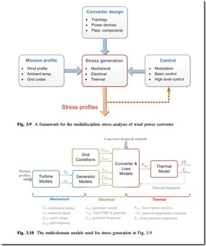
As mentioned before, the thermal stress of power semiconductors is influenced by many factors and may involve multidisciplinary approaches to analyze. As shown in Fig. 3.9, a potential framework for the multidiscipline stress analysis is estab- lished, where the determining factors that have impacts to the loadings of the converter are divided into three groups: 1. The factors of mission profile which includes the wind speed or ambient temperature variations as well as the grid conditions. 2. The factors of converter design which relates to the used topologies, power semiconductors, and passive components. 3. The factors of controls which involve the modulation or power control strategies of converter/turbine. It is noted that in this analysis framework, a series of multi-domain models are necessary to translate the stress-determining factors into the corresponding stress profiles of the converter, as highlighted by the “Stress generation” block in Fig. 3.9.
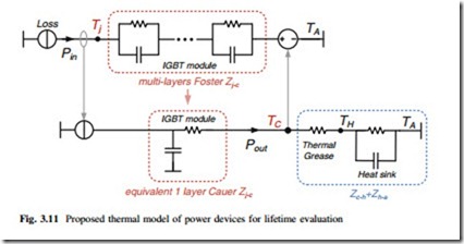
The multi-domain models used for stress generation are detailed in Fig. 3.10, where the mechanical, electrical, and thermal behaviors of the wind turbine system
are characterized, respectively. It can be seen that these models are not independent but closely related to each other by the parameters indicated in Fig. 3.10.
The wind turbine and the generator models, which are used to translate the wind speeds into the electrical power flowing into the power converter, are listed in Sect. 7.1 for simplicity, while the loss and thermal models which are critical for the stress estimation in power semiconductor devices are detailed as follows:
A. Loss Model
The loss model of the power semiconductors can transfer the electrical loading subjected to the devices (i.e., current and voltage) into the power losses generated on the semiconductor chips or junction. The used loss model in this monograph is a widely accepted method which is detailed in [12–14]. The estimated losses are based on the datasheet parameters of the selected power switching devices and they are normally temperature dependent. Therefore in order to get a relative more accurate loss estimation, the mean junction temperature from the outputs of the thermal model has to be feedback for iteration, as also illustrated in Fig. 3.10. However, sometimes for simplicity, approximated estimation or lack of information from datasheets, the temperature dependency of the loss model is not considered and the worst junction temperature condition (normally at 125 °C) is assumed.
The thermal model for power semiconductors devices can transfer the generated power losses on the chips or junction into the temperatures at different locations of the power devices (e.g., the junction, case, or heat sink). Normally, the thermal behavior of a certain material is represented by the thermal resistance Rth and capacitance Cth [15]. The total thermal impedance of a power switching devices from junction to ambient can be modeled as cascaded thermal RC networks rep- resenting different material layers as shown in Fig. 3.2.
Based on the connection of thermal capacitance, the thermal RC networks may have two different forms: the first one is called Foster network which is normally provided by manufacturers on the datasheets. This thermal model is just a mathe- matical fitting of the measured external thermal behavior and do not represent any physical meaning for each RC lump [16–19]. The other one is called Cauer network which is based on the material modeling of each layer inside power devices and thereby has physical meaning for each RC lump. However, this type of Cauer network is complicated to be accurately modeled and the Finite Element Method simulation may be introduced.
According to [9], not only the junction temperature, but also the case and heat sink temperatures are important for the lifetime estimation of power semiconduc- tors. However, it is found that both of the existing thermal networks have their limits to acquire the appropriate case and heat sink temperatures, as detailed in the attached special topic: Chap. 10. As a result, a new thermal model which combines the advantages of these two thermal networks is proposed. By the proposed thermal model and simulation method, it is possible to estimate not only the junction temperature but also the case and heat sink temperature in a relative longer time period for the reliability evaluation. The proposed thermal model is shown in Fig. 3.11; it can be seen that it contains two paths for the thermal flow. The first one is used for junction temperature estimation and the second one is used for case and heat sink temperature estimation.
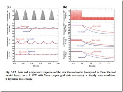
When applying the proposed thermal model to a designed 1-MW grid side converter in Chap. 10., the corresponding power loss generated inside individual
IGBT Pin, power loss output from IGBT base plate Pout, as well as the IGBT junction temperature Tj and case temperature TC are shown in Fig. 3.12a, in which the behaviors of the equivalent Cauer thermal model are also indicated as a com- parison. It can be seen that under the same generated power loss Pin, the proposed new thermal model can achieve almost the same junction and case temperatures at steady state as the Cauer thermal model, with less filtered Pout. Figure 3.12b shows a dynamic change of the converter loading from rated 1 MW to 0.2 MW output at
the 0.6 s. It can be seen that the new thermal model can achieve faster thermal response in the Pout, TC, and Tj. The advantages and results of this thermal model are further explained in the attached special topic Chap. 10.


