Capacitors provide tremendous benefits to distribution system performance. Most noticeably, capacitors reduce losses, free up capacity, and reduce volt- age drop:
• Losses; Capacity — By canceling the reactive power to motors and other loads with low power factor, capacitors decrease the line cur- rent. Reduced current frees up capacity; the same circuit can serve more load. Reduced current also significantly lowers the I2R line losses.
• Voltage drop — Capacitors provide a voltage boost, which cancels part of the drop caused by system loads. Switched capacitors can regulate voltage on a circuit.
If applied properly and controlled, capacitors can significantly improve the performance of distribution circuits. But if not properly applied or con- trolled, the reactive power from capacitor banks can create losses and high voltages. The greatest danger of overvoltages occurs under light load. Good planning helps ensure that capacitors are sited properly. More sophisticated controllers (like two-way radios with monitoring) reduce the risk of improp- erly controlling capacitors, compared to simple controllers (like a time clock). Capacitors work their magic by storing energy. Capacitors are simple devices: two metal plates sandwiched around an insulating dielectric. When charged to a given voltage, opposing charges fill the plates on either side of the dielectric. The strong attraction of the charges across the very short distance separating them makes a tank of energy. Capacitors oppose changes in voltage; it takes time to fill up the plates with charge, and once charged, it takes time to discharge the voltage.
On ac power systems, capacitors do not store their energy very long — just one-half cycle. Each half cycle, a capacitor charges up and then discharges its stored energy back into the system. The net real power transfer is zero. Capacitors provide power just when reactive loads need it. Just when a motor with low power factor needs power from the system, the capacitor is there to provide it. Then in the next half cycle, the motor releases its excess
energy, and the capacitor is there to absorb it. Capacitors and reactive loads
exchange this reactive power back and forth. This benefits the system because that reactive power (and extra current) does not have to be trans- mitted from the generators all the way through many transformers and many miles of lines; the capacitors can provide the reactive power locally. This frees up the lines to carry real power, power that actually does work.
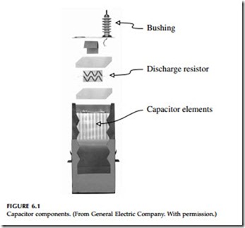
Capacitor units are made of series and parallel combinations of capacitor packs or elements put together as shown in Figure 6.1. Capacitor elements have sheets of polypropylene film, less than one mil thick, sandwiched between aluminum foil sheets. Capacitor dielectrics must withstand on the order of 2000 V/mil (78 kV/mm). No other medium-voltage equipment has such high voltage stress. An underground cable for a 12.47-kV system has insulation that is at least 0.175 in. (4.4 mm) thick. A capacitor on the same system has an insulation separation of only 0.004 in. (0.1 mm).
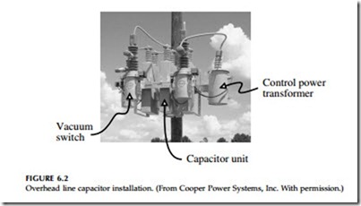
Utilities often install substation capacitors and capacitors at points on distribution feeders. Most feeder capacitor banks are pole mounted, the least expensive way to install distribution capacitors. Pole-mounted capacitors normally provide 300 to 3600 kvar at each installation. Many capacitors are switched, either based on a local controller or from a centralized controller through a communication medium. A line capacitor installation has the capacitor units as well as other components, possibly including arresters, fuses, a control power transformer, switches, and a controller (see Figure 6.2 for an example).
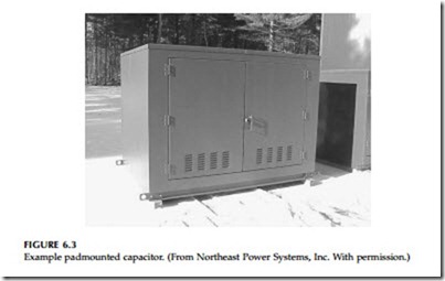
While most capacitors are pole mounted, some manufacturers provide padmounted capacitors. As more circuits are put underground, the need for padmounted capacitors will grow. Padmounted capacitors contain capacitor cans, switches, and fusing in a deadfront package following standard pad- mounted-enclosure integrity requirements (ANSI C57.12.28-1998). These units are much larger than padmounted transformers, so they must be sited more carefully to avoid complaints due to aesthetics. The biggest obstacles are cost and aesthetics. The main complaint is that padmounted capacitors are large. Customers complain about the intrusion and the aesthetics of such a large structure (see Figure 6.3).
Substation capacitors are normally offered as open-air racks. Normally elevated to reduce the hazard, individual capacitor units are stacked in rows to provide large quantities of reactive power. All equipment is exposed. Stack racks require a large substation footprint and are normally engineered for the given substation. Manufacturers also offer metal-enclosed capacitors, where capacitors, switches, and fuses (normally current-limiting) are all enclosed in a metal housing.
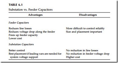
Substation capacitors and feeder capacitors both have their uses. Feeder capacitors are closer to the loads — capacitors closer to loads more effectively release capacity, improve voltage profiles, and reduce line losses. This is especially true on long feeders that have considerable line losses and voltage drop. Table 6.1 highlights some of the differences between feeder and station capacitors. Substation capacitors are better when more precise control is needed. System operators can easily control substation capacitors wired into a SCADA system to dispatch vars as needed. Modern communication and control technologies applied to feeder capacitors have reduced this advantage. Operators can control feeder banks with communications just like station banks, although some utilities have found the reliability of switched feeder banks to be less than desired, and the best times for switching in vars needed by the system may not correspond to the best time to switch the capacitor in for the circuit it is located on.
Substation capacitors may also be desirable if a leading power factor is needed for voltage support. If the power factor is leading, moving this capac- itor out on the feeder increases losses. Substation capacitors cost more than feeder capacitors. This may seem surprising, but we must individually engi- neer station capacitors, and the space they take up in a station is often valuable real estate. Pole-mounted capacitor installations are more standardized.
Utilities normally apply capacitors on three-phase sections. Applications on single-phase lines are done but less common. Application of three-phase banks downstream of single-phase protectors is normally not done because
of ferroresonance concerns. Most three-phase banks are connected grounded-wye on four-wire multigrounded circuits. Some are connected in floating wye. On three-wire circuits, banks are normally connected as a floating wye.
Most utilities also include arresters and fuses on capacitor installations. Arresters protect capacitor banks from lightning-overvoltages. Fuses isolate failed capacitor units from the system and clear the fault before the capacitor fails violently. In high fault-current areas, utilities may use current-limiting fuses. Switched capacitor units normally have oil or vacuum switches in addition to a controller. Depending on the type of control, the installation may include a control power transformer for power and voltage sensing and possibly a current sensor. Because a capacitor bank has a number of compo- nents, capacitors normally are not applied on poles with other equipment. Properly applied capacitors return their investment very quickly. Capacitors save significant amounts of money in reduced losses. In some cases, reduced loadings and extra capacity can also delay building more distribution infrastructure.


