Malfunctions
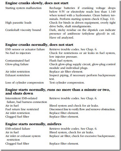
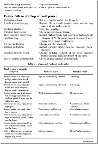
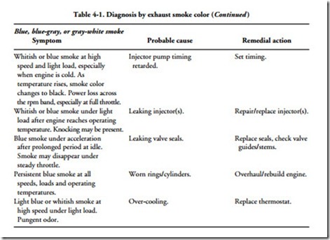
Common malfunctions are listed below together with probable causes and remedial actions. Fuel-related malfunctions can affect the color of the exhaust smoke, as indicated in Table 4-1. When taken together, engine behavior and smoke color provide a good indication of the source of the problem.
Tests
Fuel quality
Take a fuel sample from some convenient point upstream of the filter/water separator. Allow the fuel to settle for a few minutes in a glass container and inspect for cloudiness (an indication of water), algae (jellylike particles floating on the sur- face), and solids. Placing a few drops of fuel between two pieces of glass will make it easier to see impurities. If fuel appears contaminated, drain and purge the system as described below.
Assuming that the fuel is clean and water-free, the most important quality is its cetane value, which can be determined with fuel hydrometer. A good No. 2 diesel has a specific gravity of 0.840 or higher at 60°F. No. 1 diesel can reduce power out- puts by as much as 7% over No. 2 fuel. Blending the two fuels, a common practice in cold climates, results in correspondingly less power.
Fuel system
Most failures involve the fuel system. This system consists of three circuits, each operating at a different pressure.
• Low-pressure circuit. This includes the tank strainer, in-tank pump (on many vehicles), water-fuel separator, filter(s), and lift pump. Pressures vary with the application, but rarely exceed 75 psi.
• Fuel-return circuit. Operating at almost zero pressure, the return line con- veys surplus fuel from the injectors back to the tank, filter, or to the inlet side of injector pump. Many of these systems include a restrictor orifice between the fuel-supply line and the return line. The orifice can clog, closing off the fuel return. Air leaks become a matter of concern when fuel is returned to the filter or injector pump, and not to the tank.
High-pressure circuit. As shown in Fig. 4-1, the high-pressure circuit con- nects the discharge side of the injector pump with the injectors. For many applications, the connecting plumbing takes the form of dedicated lines from pump to the individual injectors. A more modern approach is to supply the injectors from a common manifold, or rail. The third alternative does away with the external high-pressure circuit by employing unit injectors (UIs). Each UI is a self-contained unit, with its own high-pressure pump operated by an engine-driven camshaft or, in the case of the Hydraulic Electronic Unit Injector (HEUI), by oil pressure. The unit pump system (UPS) is a hybrid, with each injector served by a dedicated pump plunger operating off the engine camshaft. Plunger-to-injector lines are pressurized.


