Basic Principles
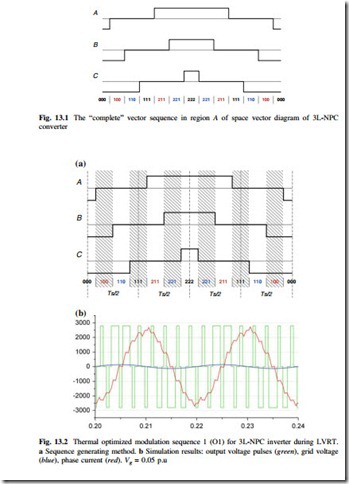
In order to reduce the output time for zero voltage level of 3L-NPC inverter during LVRT, a direct and basic idea is trying to generate a special vector sequence which avoids using the state vector “111,” (because state vector 111 outputs zero voltage level for all of the three phases). Following the two criteria for generating the modulation sequences and avoiding use of the state vector 111, one way to synthesize the desired voltage reference is to choose the state vectors 000, 110, 211, 222 based on the “unique” vector sequence is shown in Fig. 13.1. The special modulation sequence is generated in Fig. 13.2a, which is called Optimized sequence 1 (O1) for convenience. The gray blocks indicate the eliminated redundant state vectors.
The simulation results of this optimized sequence are shown in Fig. 13.2b. It can be seen that the output voltage of this modulation sequence alternates between positive, zero, negative voltage levels within neighboring switching cycles, which is quite different from the traditional three-level output pattern of 3L-NPC converter. Also the amplitude and phase angle of the load current are kept unchanged. After modification, the average voltage reference will be kept unchanged, but the duration time of the zero voltage level is significantly reduced, and the widths of both positive and negative output voltage pulses are expanded.
It is noticed that the equivalent switching frequency is doubled by the optimized modulation sequence O1, the carrier frequency thereby needs to be adjusted to half in order to acquire the same switching frequency as the normal SVM sequence.
