Voltage regulation with Zener Diodes
A zener diode can be used to stabilize or regulate volt- age. For example, it can be used to compensate for power-line voltage changes or load-resistance changes while maintaining a constant DC output.
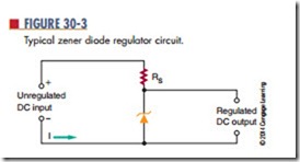
Figure 30-3 shows a typical zener diode regulator circuit. The zener diode is connected in series with resistor RS. The resistor allows enough current to flow for the zener diode to operate in the zener breakdown region. The DC input voltage must be higher than the zener diode breakdown voltage. The voltage drop –across the zener diode is equal to the zener diode’s voltage rating. Zener diodes are manufactured to
have a specific breakdown voltage rating that is often referred to as the diode’s zener voltage rating (eZ). The voltage drop across the resistor is equal to the difference between the zener (breakdown) voltage and the input voltage.
The input voltage may increase or decrease. This causes the current through the zener diode to increase or decrease accordingly. When the zener diode is operating in the zener voltage, or breakdown region, a large current flows through the zener, with an increase in input voltage. However, the zener voltage remains the same. The zener diode opposes an increase in input voltage, because when the current increases, the resistance drops. This allows the zener output voltage of the zener diode to remain constant as the input voltage changes. The change in the input volt- age appears across the series resistor. The resistor is in series with the zener diode, and the sum of the voltage drop must equal the input voltage. The output voltage is taken across the zener diode.
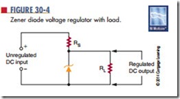
The output voltage can be increased or decreased by changing the zener diode and the series resistor. The circuit just described supplies a constant volt- age. When a circuit is designed, the current in the circuit must be considered as well as the voltage. The xternal load requires a specific load current (iL) determined by the load resistance and output voltage (Figure 30-4). The load current and the zener current
flow through the series resistor. The series resistor must be chosen so that the zener current is adequate to keep the zener diode in the breakdown zone and allow the current to flow.
When the load resistance increases, the load cur- rent decreases, which should increase the voltage across the load resistance. But the zener diode opposes any change by conducting more current. The sum of the zener current and the load current through the series resistor remains constant. This action maintains the same voltage across the series resistor.
Similarly, when the load current increases, the zener current decreases, maintaining a constant voltage. This action allows the circuit to regulate for change in output current as well as input voltage.
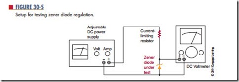
do not provide information on whether the zener diode is regulating at the rated value. For that information, a regulation test must be performed with a metered power supply that can indicate both voltage and current.
Figure 30-5 shows the proper setup for a zener diode regulation test. The output of the power sup- ply is connected with a limiting resistor in series with a zener diode to be tested. A voltmeter is connected across the zener diode under test to monitor the zener voltage. The output voltage is slowly increased until the specified current is flowing through the zener diode. The current is then varied on either side of the specified zener current (IZ). If the voltage remains constant, the zener diode is operating properly.
Questions
1. What is a practical function for a zener diode?
2. Draw a schematic diagram of a zener diode regulator circuit.
3. How can the voltage of a zener diode voltage regulator circuit be changed?
4. What must be considered in designing a zener diode voltage regulator?
5. Describe how a zener diode voltage regulator maintains a constant output voltage.


