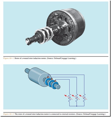
The wound rotor induction motor is one of the three major types of three-phase motors. It is often called the slip ring motor because of the three slip rings on the rotor shaft. The stator winding of a wound rotor motor is identical to the squirrel cage motor. The difference be- tween the two motors lies in the construction of the rotor. The rotor of a squirrel cage motor is constructed of bars connected together at each end by shorting rings. The rotor of a wound rotor induction motor is constructed by winding three separate windings in the rotor (Figure 44 – 1).
The wound rotor motor was the first alternating current motor that permitted speed control. It has a higher starting torque per ampere of starting current than any other type of three-phase motor. It can be started in multiple steps to provide smooth acceleration from 0 RPM to maximum RPM. Wound rotor motors are typically employed to operate conveyors, cranes, mixers, pumps, variable speed fans, and a variety of other devices. They are often used to power gear driven machines because they can be started without supplying a large amount of torque that can damage and even strip the teeth off gears.
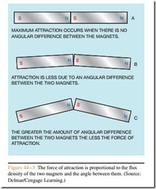
The three-phase rotor winding will contain the same number of poles as the stator winding. One end of each rotor winding is connected together inside the rotor to form a wye connection, and the other end of each wind- ing is connected to one of the slip rings mounted on the rotor shaft. The slip rings permit external resistance to be connected to the rotor circuit (Figure 44 – 2). Placing external resistance in the rotor circuit allows control of the amount of current that can flow through the rotor windings during both the starting and running of the motor. There are three factors that determine the amount of torque developed by a three-phase induction motor:
• Strength of the magnetic field of the stator.
• Strength of the magnetic field of the rotor.
• Phase angle difference between rotor and stator flux.
Since an induction motor is basically a transformer, controlling the amount of rotor current also controls the amount of stator current. It is this feature that permits the wound rotor motor to control the in-rush cur- rent during the starting period. Limiting the in-rush current also limits the amount of starting torque produced by the motor.
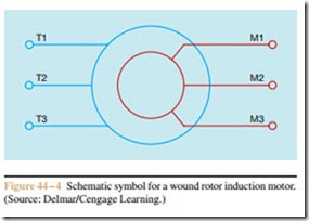
The third factor that determines the amount of torque developed is the phase angle difference between stator and rotor flux. Maximum torque is developed when the magnetic fields of the stator and rotor are in phase with each other. Imagine two bar magnets with their north and south poles connected together. If the magnets are placed so there is no angular difference
between them (Figure 44 – 3A), the attracting force is at maximum. If the magnets are broke apart so there is an angular difference between them, there is still a force of attraction, but it is less than when they are connected together (Figure 44 – 3B). The greater the angle of separation, the less the force of attraction becomes (Figure 44 – 3C).
Adding resistance to the rotor circuit causes the induced current in the rotor to be more in phase with the stator current. This produces a very small phase angle difference between the magnetic fields of the rotor and stator. This is the reason that the wound rotor induction motor produces the greatest amount of starting torque per ampere of starting current of any three-phase motor.
The stator windings of a wound rotor motor are marked in the same manner as any other three-phase motor: T1, T2, and T3 for single voltage motors. Dual voltage motors will have nine T leads, like squirrel cage motors. The rotor leads are labeled M1, M2, and M3. The M2 lead is located on the center slip ring and the M3 lead is connected to the slip ring closest to the rotor windings. The schematic symbol for a wound rotor induction motor is shown in Figure 44 – 4.
Manual Control of a Wound Rotor Motor
The starting current and speed of a wound rotor induction motor is controlled by adding or subtracting the amount of resistance connected in the rotor circuit. Small wound rotor motors are often controlled manually by a three-pole make-before-break rotary switch. The switch will contain as many contacts as there are steps of resistance (Figure 44 – 5). A micro limit switch senses when the controller is set for maximum resistance. Most controllers will not start unless all resistance is in the rotor circuit, forcing the motor to start in its lowest speed. Once the motor has been started, the resistance can then be adjusted out to increase the motor speed. When all the resistance has been removed from the circuit and the M leads are shorted together, the motor will operate at full speed. The operating characteristics of a wound rotor motor with the rotor leads shorted together are very similar to those of a squirrel cage motor. A circuit for use with a manual controller is shown in Figure 44 – 6.


