Television Signal
The television signal must do two things, the first is obvious, the second less so. First, it must control the instantaneous brightness of the spot on the face of the CRT in order that the brightness changes that constitute the information of the picture may be conveyed. Second, it must control the raster scanning so that the beam travels across the tube face in synchronism with the tube within the transmitting camera. Otherwise information from the top left-hand side of the televised scene will not appear in the top left-hand side of the screen and so on! In the analogue television signal this distinction between picture information and scan synchronizing information (known in the trade as sync-pulse information) is divided by a voltage level known as black level. All information above black level relates to picture information, whereas all information below relates to sync information. By this clever means, all synchronizing information is “below” black level. The electron beam therefore remains cut off—and the screen remains dark—during the sync information. In digital television the distinction between data relating to picture modulation and sync is established by a unique codeword preamble, which identifies the following byte as a sync byte.
Horizontal and Vertical Sync
The analogy between the eye’s movement across the page during reading and the movement of the scan spot in scanning a tube face has already been made. Of course the scan spot doesn’t move onto another page like the eyes do once they have reached the bottom of the page, but it does have to fly back to start all over again once it has completed one whole set of lines from the top to the bottom of the raster. The spot thus flies back in two possible ways: a horizontal retrace, between lines, and a vertical retrace, once it has completed one whole set of lines and is required to start all over again on another set. Obviously to stay in synchronism with the transmitting camera the television receiver must be instructed to perform both horizontal retrace and vertical retrace at the appropriate times—and furthermore not to confuse one instruction for the other!
It is for this reason that there exist two types of sync information known reasonably enough as horizontal and vertical. Inside the television monitor these are treated separately and respectively initiate and terminate the horizontal and vertical scan generator circuits. These circuits are similar—at least in principle—to the ramp or sawtooth generator circuits. As the current gradually increases in both horizontal and vertical scan coils, the spot is made to move from left to right and top to bottom, the current in the top to bottom circuit growing 312.5 times more slowly than in the horizontal deflection coils so that 312.5 lines are drawn in the time it takes the vertical deflection circuit to draw the beam across the vertical extent of the tube face.
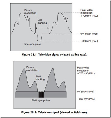
The complete television signal is illustrated in Figures 28.1 and 28.2, which display the signal using two different time bases. Note the amplitude level, which distinguishes the watershed between picture information and sync information. Known as black level, this voltage is set to a standard 0 V. Peak white information is defined not to go beyond a level of 0.7 V above this reference level. Sync information, the line or horizontal sync, 4.7-μs pulse is visible in the figure and should extend 0.3 V below the black reference level. Note also that the picture information falls to the black level before and after the sync pulse. This interval is necessary because the electron beam cannot instantaneously retrace to the left-hand side of the screen to
restart another trace. It takes a little time—about 12 μs. This period, which includes duration of the 4.7-μs line-sync pulse during which time the beam current is controlled “blacker than black,” is known as the line-blanking period. A similar, much longer, period exists to allow the scan spot to return to the top of the screen once a whole vertical scan has been accomplished; this interval is known as the field blanking or vertical interval.
Looking now at Figure 28.2, a whole 625 lines are shown, in two fields of 312.5 lines. Note the wider sync pulses that appear between each field. In order that a monitor may distinguish between horizontal and vertical sync, the duration of line-sync pulses is extended during the vertical interval (the gap in the picture information allowing for the field retrace), and a charge-pump circuit combined with a comparator is able to detect these longer pulses as different from the shorter line-sync pulses. This information is sent to the vertical scan generator to control the synchronism of the vertical scan.
