Analogue Video Interfaces
Due to their wide bandwidth, analogue television signals are always distributed via coaxial cables. The technique known as matched termination is universally applied. In this scheme, both the sender impedance and the load impedance are set to match the surge impedance of the line itself. This minimizes reflections. Standard impedance in television is 75 Ω. A typical interconnection is shown in Figure 28.9. Note that matched termination has the one disadvantage that the voltage signal arriving across the receiver’s termination is half that of the signal EMF provided by the sender. Standard voltage levels (referred to earlier) always relate to voltages measured across the termination impedance.
Digital Video
In order to see the forces that have led to the rapid adoption of digital video processing and interfacing throughout the television industry in the 1990s, it is necessary to look at some of the technical innovations in television during the late 1970s and early 1980s.
The NTSC and PAL television systems described earlier were developed primarily as transmission standards, not as television production standards. As we have seen, because of the nature of the NTSC and PAL signal, high-frequency luminance detail can easily translate to erroneous color information. In fact, this cross-color effect is an almost constant feature of the broadcast standard television pictures and results in a general “business” to the picture at all times. That said, these composite TV standards (so named because the color and luminance information travel in a composite form) became the primary production standard mainly due to the inordinate cost of “three- level” signal processing equipment (i.e., routing switchers, mixers), which operated on the red, green, and blue or luminance and color-difference signals separately. A further consideration, beyond cost, was that it remained difficult to keep the gain, DC offsets, and frequency response (and therefore delay) of such systems constant, or at least consistent, over relatively long periods of time. Systems that did treat the R, G, and B components separately suffered particularly from color shifts throughout the duration of a program. Nevertheless, as analogue technology improved, with the use of integrated circuits as opposed to discrete semiconductor circuits, manufacturers started to produce three-channel, component television equipment that processed the luminance, R-Y and B – Y signals separately. Pressure for this extra quality came particularly from graphics areas, which found that working with the composite standards resulted in poor quality images that were tiring to work on, and where they wished to use both fine detail textures, which created cross-color, and heavily saturated colors, which do not produce well on a composite system (especially NTSC).
So-called analogue component television equipment had a relatively short stay in the world of high-end production largely because the problems of intercomponent levels, drift, and frequency response were never ultimately solved. A digital system, of course, has no such problems. Noise, amplitude response with respect to frequency, and time are immutable parameters “designed into” the equipment—not parameters that shift as currents change by fractions of milliamps in a base-emitter junction somewhere! From the start, digital television offered the only real alternative to analogue composite processing and, as production houses were becoming dissatisfied with the production value obtainable with composite equipment, the death knell was dealt to analogue processing in television.
The 4:2:2 Protocol Description—General
Just as with audio, so with video, as more and more television equipment began to process the signals internally in digital form, so the number of conversions could be kept to a minimum if manufacturers provided a digital interface standard allowing various pieces of digital video hardware to pass digital video information directly without recourse to standard analogue connections. This section is a basic outline of the 4:2:2 protocol (otherwise known as CCIR 601), which has been accepted as the industry standard for digitized component TV signals. The data signals are carried in the form of binary information coded in 8- or 10-bit words. These signals comprise the video signals
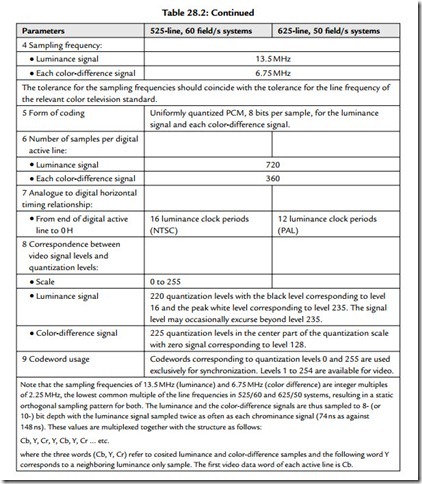
themselves and timing reference signals. Also included in the protocol are ancillary data and identification signals. The video signals are derived by coding of the analogue video signal components. These components are luminance (Y) and color difference (Cr and Cb) signals generated from primary signals (R, G, B). The coding parameters are specified in CCIR Recommendation 601 and the main details are reproduced in Table 28.2.
Timing Relationships
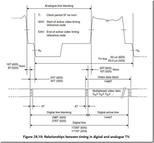
The digital active line begins at 264 words from the leading edge of the analogue line synchronization pulse; this time is specified between half amplitude points. This relationship is shown in Figure 28.10. The start of the first digital field is fixed by the
position specified for the start of the digital active line: the first digital field starts at 24 words before the start of the analogue line No. 1. The second digital field starts 24 words before the start of analogue line No. 313.
Video Timing Reference Signals (TRS)
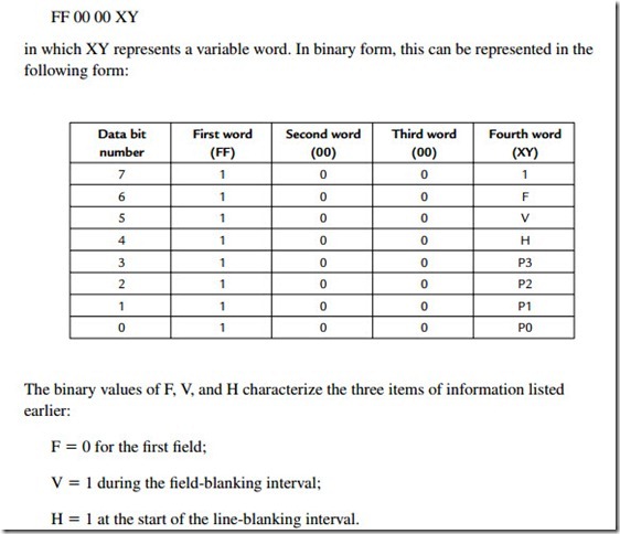
Two video TRS are multiplexed into the data stream on every line, as shown in Figure 28.10, and retain the same format throughout the field blanking interval. Each timing reference signal consists of a four-word sequence, with the first three words being a fixed preamble and the fourth containing the information defining:
First and second field blanking; State of the field blanking;
Beginning and end of the line blanking.
This sequence of four words can be represented, using hexadecimal notation, in the following manner:
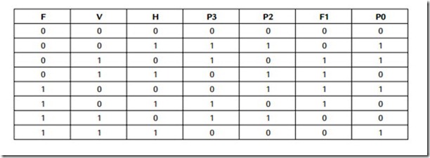
The binary values P0, P1, P2, and P3 depend on the states of F, V, and H in accordance with the following table and are used for error detection/correction of timing data:
Clock Signal
The clock signal is at 27 MHz, there being 1728 clock intervals during each horizontal line period (PAL).
Filter Templates
The remainder of CCIR Recommendation 601 is concerned with the definition of the frequency response plots for presampling and reconstruction filter. The filters required by Recommendation 601 are practically difficult to achieve and equipment required to meet this specification has to contain expensive filters in order to obtain the required performance.
Parallel Digital Interface
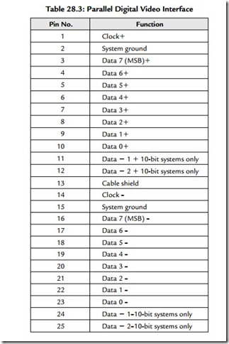
The first digital video interface standards were parallel in format. They consisted of 8 or 10 bits of differential data at ECL data levels and a differential clock signal again as an ECL signal. Carried via a multicore cable, the signals terminated at either end in a standard D25 plug and socket. In many ways this was an excellent arrangement and is well suited to connecting two local digital videotape machines together over a short distance. The protocol for the digital video interface is shown in Table 28.3. Clock transitions are specified to take place in the center of each data-bit cell.
Problems arose with the parallel digital video interface over medium/long distances, resulting in misclocking of input data and visual “sparkles” or “zits” on the picture.
Furthermore, the parallel interface required expensive and nonstandard multicore cable (although over very short distances it could run over standard ribbon cable) and the D25 plug and socket are very bulky. Today, the parallel interface standard has been largely superseded by the serial digital video standard, which is designed to be transmitted over relatively long distances using the same coaxial cable as used for analogue video signals. This makes its adoption and implementation as simple as possible for existing television facilities converting from analogue to digital video standards.
Serial Digital Video Interface
SMPTE 259M specifies the parameters of the serial digital standard. This document specifies that parallel data in the format given in the previous section be serialized and transmitted at a rate 10 times the parallel clock frequency. For component signals, this is
Serialized data must have a peak-to-peak amplitude of 800 mV (±10%) across 75 Ω, have a nominal rise time of 1 ns, and have a jitter performance of ±250 ps. At the receiving end, signals must be converted back to parallel in order to present original parallel data to the internal video processing. (Note that no equipment processes video in its serial form, although digital routing switchers and DAs, where there is no necessity to alter the signal, only buffer it or route it, do not decode the serial bit stream.)
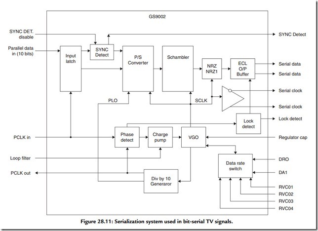
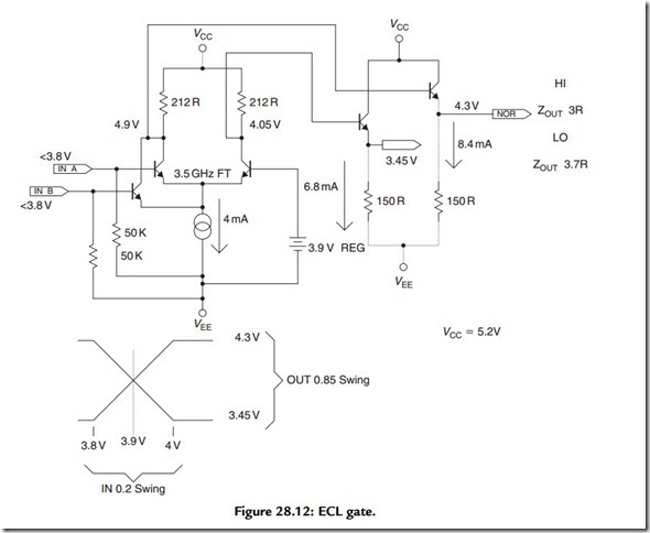
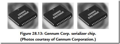
Serialization is achieved by means of a system illustrated in Figure 28.11. Parallel data and a parallel clock are fed into input latches and then to a parallel to serial conversion circuit. The parallel clock is also fed to a phase-locked loop, which performs parallel clock multiplication (by 10 times). A sync detector looks for TRS information and ensures that this is encoded correctly irrespective of 8- or 10-bit resolution. Serial data are fed out of the serializer and into the scrambler and NRZ to NRZI circuit. The scrambler circuit uses a linear feedback shift register, which is used to pseudo-randomize incoming serial data. This has the effect of minimizing the DC component of the output serial data stream, the NRZ to NRZI circuit converts long series of ones to a series of transitions. The resulting signal contains enough information at clock rate and is sufficiently DC free that it may be sent down existing video cables. It may be then be reclocked, decoded, and converted back to parallel data at the receiving equipment. Because of its very high data rate, serial video must be carried by ECL circuits. An illustration of a typical ECL gate is given in Figure 28.12. Note that standard video levels are commensurate with data levels in ECL logic. Clearly the implementation of such a high-speed interface is a highly specialized task. Fortunately, practical engineers have all the requirements for interface encoders and decoders designed for them by third-party integrated circuit manufacturers (Figure 28.13).
Embedded Digital Audio in the Digital Video Interface
So far, we have considered the interfacing of digital audio and video separately. Manifestly, there exist many good operational reasons to combine a television picture with its accompanying sound “down the same wire.” The standard that specifies the embedding of digital audio data, auxiliary data, and associated control information into the ancillary data space of the serial digital interconnect conforming to SMPTE 259M in this manner is the proposed SMPTE 272M standard.
The video standard has adequate “space” for the mapping of a minimum of 1 stereo digital audio signal (or two mono channels) to a maximum of 8 pairs of stereo digital audio signals (or 16 mono channels). The 16 channels are divided into 4 audio signals in 4 “groups.” The standard provides for 10 levels of operation (suffixed A to J), which allow for various different and extended operations over and above the default synchronous 48-kHz/20-bit standard. The audio may appear in any and/or all the line blanking periods and should be distributed evenly throughout the field. Consider the case of one 48-kHz audio signal multiplexed into a 625/50 digital video signal. The number of samples to be transmitted every line is:
which is equivalent to 3.072 samples per line. The sensible approach is taken within the standard of transmitting 3 samples per line most of the time and transmitting 4 samples per line occasionally in order to create this noninteger average data rate. In the case of 625/50, this leads to 1920 samples per complete frame. (Obviously a comparable calculation can be made for other sampling and frame rates.) All that is required to achieve this “packeting” of audio within each video line is a small amount of buffering
either end and a small data overhead to “tell” the receiver whether it should expect 3 or 4 samples on any given line.
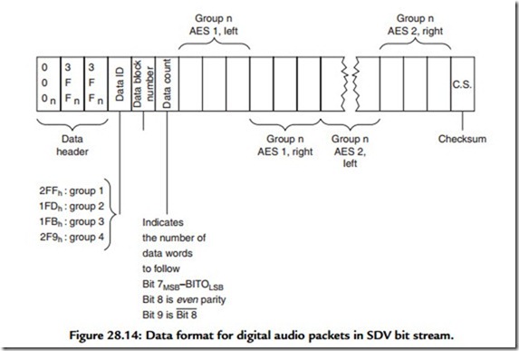
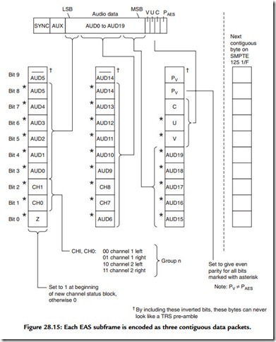
Figure 28.14 illustrates the structure of each digital audio packet as it appears on preferably all, or nearly all, the lines of the field. The packet starts immediately after the TRS word for EAV (end of active line) with the ancillary data header 000,3FF,3FF. This is followed by a unique ancillary data ID, which defines which audio group is being transmitted. This is followed with a data-block number byte. This is a free-running counter counting from 1 to 255 on the lowest 8 bits. If this is set to zero, a deembedder is to assume that this option is not active. The 9th bit is even parity for b7 to b0 and the 10th is the inverse of the 9th. It is by means of this data-block number word that a vertical interval switch could be discovered and concealed. The next word is a data count, which indicates to a receiver the number of audio data words to follow. Audio subframes then follow as adjacent sets of three contiguous words. The format in which each AES subframe is encoded is illustrated in Figure 28.15. Each audio data packet terminates in a checksum word.
The standard also specifies an optional audio control packet. If the control packet is not transmitted, a receiver defaults to 48 kHz, synchronous operation. For other levels, the control byte must be transmitted in field interval.
Time Code
Longitudinal Time Code (LTC)
As we have seen, television (like movie film) gives the impression of continuous motion pictures by the successive, swift presentation of still images, thereby fooling the eye into believing it is perceiving motion. It is probably therefore no surprise that time code (deriving as it does from television technology) operates by “tagging” each video frame with a unique identifying number called a time code address. The address contains information concerning hours, minutes, seconds, and frames. This information is formed into a serial digital code, which is recorded as a data signal onto one of the audio tracks of a videotape recorder. (Some videotape recorders have a dedicated track for this purpose.)
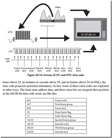
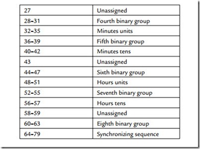
Each frame’s worth of data is known as a word of time code and this digital word is formed of 80 bits spaced evenly throughout the frame. Taking the European Broadcasting Union (EBU) time code3 as an example, the final data rate therefore turns out to be 80 bits X 25 frames per second = 2000 bits per second, which is equivalent to a fundamental frequency of 1 kHz; easily low enough, therefore, to be treated as a straightforward audio signal. The time code word data format is illustrated (along with its temporal relationship to a video field) in Figure 28.16. The precise form of the electrical code for time code is known as Manchester biphase modulation. When used in a video environment, time code must be accurately phased to the video signal. As defined in the specification, the leading edge of bit ‘0’ must begin at the start of line 5 of field 1 (±1 line). Time address data are encoded within the 80 bits as 8, 4-bit BCD (binary coded decimal) words (i.e., 1, 4-bit number for tens and 1 for units). Like the clock itself, time address data are only permitted to go from 00 hours, 00 minutes, 00 seconds, 00 frames to 23 hours, 59 minutes, 59 seconds, 24 frames.
However, a 4-bit BCD number can represent any number from 0 to 9, so in principle, time code could be used to represent 99 hours, 99 minutes, and so on. But, as there are no
Vertical Interval Time Code (VITC)
LTC is a quasi-audio signal recorded on an audio track (or hidden audio track dedicated to time code). VITC, however, encodes the same information within the vertical interval portion of the video signal in a manner similar to a Teletext signal. Each has advantages and disadvantages; LTC is unable to be read while the player/ recorder is in pause, while VITC cannot be read while the machine is in fast forward or rewind modes. It is advantageous that a videotape has both forms of time code recorded. VITC is also illustrated in Figure 28.16. Note how time code is displayed “burned in” on the monitor.
PAL and NTSC
Naturally, time code varies according to the television system used, and for NTSC (SMPTE) there are two versions of time code in use to accommodate the slight difference between the nominal frame rate of 30 frames per second and the actual frame rate of NTSC of 29.97 frames per second. While every frame is numbered and no frames are ever actually dropped, the two versions are referred to as “drop”- and “nondrop”-frame time code. Nondrop-frame time code will have every number for every second present, but will drift out of relationship with clock time by 3.6 seconds every hour. Drop-frame time code drops numbers from the numbering system in a predetermined sequence, so that the time code-time and clock time remain in synchronization. Drop frame is important in broadcast work, where actual program time is important.
User Bits
Within the time code word there is provision for the hours, minutes, seconds, frames, and field ID that we normally see and “user bits,” which can be set by the user for additional identification. Use of user bits varies with some organizations using them to identify shoot dates or locations and others ignoring them completely.
