IGBTs
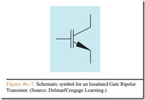
Many transistor controlled variable frequency drives now employ a special type of transistor called an Insulated Gate Bipolar Transistor (IGBT). IGBTs have an insulated gate very similar to some types of field effect transistors (FETs). Since the gate is insulated, it has very high impedance. The IGBT is a voltage controlled device, not a current controlled device. This gives it the ability to turn off very quickly. IGBTs can be driven into saturation to provide a very low voltage drop between emitter and collector, but they do not suffer from the slow recovery time of common junction transistors. The schematic symbol for an IGBT is shown in Figure 46 – 7.
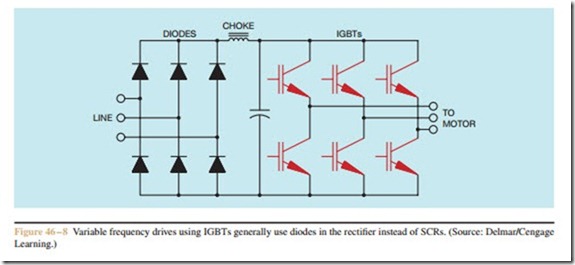
Drives using IGBTs generally use diodes, not SCRs, to rectify the AC voltage into DC (Figure 46 – 8).
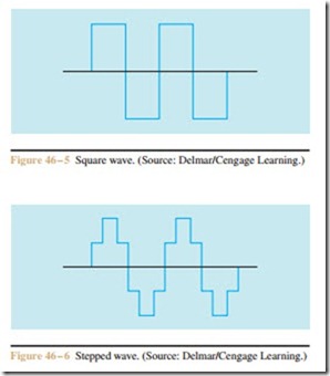
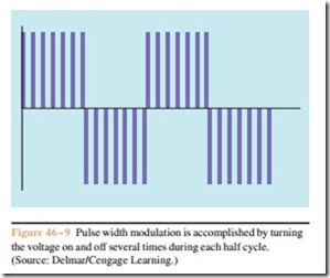
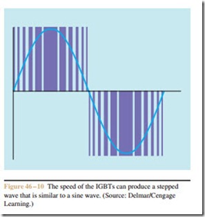
The three-phase rectifier supplies a constant DC voltage to the transistors. The output voltage to the motor is con- trolled by pulse width modulation (PWM). PWM is accomplished by turning the transistor on and off several times during each half cycle (Figure 46 – 9). The output voltage is an average of the peak or maximum voltage and the amount of time the transistor is turned on or off. Assume that 480 volts three-phase AC is rectified to DC and filtered. The DC voltage applied to the IGBTs is approximately 630 volts. The output voltage to the motor is controlled by the switching rate of the transistors. Assume that the transistor is on for 10 microseconds and off for 20 microseconds. In this example, the transistor is on for one-third of the time and off for two- thirds of the time. The voltage applied to the motor would be 210 volts (630/3). The speed at which IGBTs can operate permits pulse width modulation to produce
a stepped wave that is very similar to a standard sine wave (Figure 46 – 10).
Advantages and Disadvantages of IGBT Drives
A great advantage of drives using IGBTs is the fact that SCRs are generally not used in the power supply and this greatly reduces problems with line harmonics. The greatest disadvantage is that the fast switching rate of the transistors can cause voltage spikes in the range of 1600 volts to be applied to the motor. These voltage spikes can destroy some motors. Line length from the drive to the motor is of great concern with drives using IGBTs. Short line lengths are preferred.
