Electric motors present some special problems from the standpoint of control. An electric motor will try to provide the power required by a load, even if it results in self destruction. Therefore, a motor must be protected from overloads. A motor draws up to six times as much current when the rotor is not turning as it does when operating at full speed. Control contacts, and wires must be capable of carrying this high current during starting without causing damage or excessive voltage drop. If a motor should stall, the disconnect switch and control device must be capable of handling the high locked rotor current. For example, a 100 hp, 460 V, 3 phase electric motor powering an irrigation pump draws 124 A when operating at full load. The locked rotor current of the motor, however, is nearly 750 A, NEC Table 430 151. The motor starter and disconnect switch must be capable of interrupting 750 A in the event the motor stalls. If the disconnect or controller is not rated for this high level of current, it could explode the instant it is opened.
Motor circuits will’ be safe and motors will be protected provided the wiring procedures of NEC Article 430 are applied. Proper sizing of motor overload protection will ensure many years of dependable service.
A controller is simply a means of closing the circuit supplying power to an electrical motor, NEC 430 81 (a). Controlling may be accomplished manually or automatically. The simplest motor controller is an attachment plug and receptacle. This method is permitted only for portable motors rated at 1/1 hp and less, NEC Section 430 81(c). Motors larger than 113 hp are permitted to be cord connected, but the starting and stopping of the motor must be accomplished by one of the means discussed next
The branch circuit protective device, such as a circuit breaker, may serve as the controller for stationary motors, not larger than IJs hp, that are normally allowed to operate continuously. An example is a clock motor, NEC Section 430 8l(b). These motors are designed with a high impedance, and they cannot be overloaded even if the rotor stalls.
A time delay circuit breaker is permitted to serve as a motor controller, NEC Section 430 83, Exception No.2. This is frequently the case with farm machinery. Circuit breakers are subject to failure after repeated on and off cycling and, therefore, they are not the best choice for a controller. It is also difficult to size a circuit breaker small enough to provide overload protection for the motor, and still not trip due to the high inrush starting current of the motor
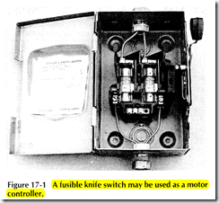
A fusible knife switch, Figure 17 1, can serve as a motor controller, provided the switch has a horsepower rating sufficient for the motor supplied, NEC Section 430 90. Time delay fuses can usually be sized small enough to provide overload protection, and still not blow during starting. The knife switch must be rated in horse power, NEC Section 430 83. The switch must also have a voltage rating sufficient for the circuit. A 250 V switch is required for motors operating at 120 V, 208 V, and 240 V. A 600 V switch is required for motors operating at 277 V or 480 V.
An ordinary snap switch rated in amperes or horsepower is permitted to be used as a controller for motors rated at not more than 2 hp, and for circuits operating at not more than 300 V, NEC Section 430 83, Exception No.1.
The general use snap switch must have an ampere rating twice that of the full load current of the motor. A 1/1 hp motor, for example, draws 7.2 A full load curren1 at 115 V. A general use snap switch with a 15 A rating would be required for this motor.
7.2 A X 2 = 14.4 A
Switches rated for use only on alternating current circuits are permitted to control motors with a full load cur· rent of 80% of the current rating of the switch. There· fore, a 30 A ac switch is permitted to supply a moto which draws 24 A.
30 A X 0.8 = 24 A
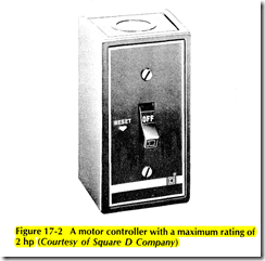
A 2 hp electric motor operating at 115 V draws 24 A Snap switches for motors are available which do pro vide overload protection, Figure 17 2. This type o switch, rather than an ordinary switch, is preferred fo controlling motors up to 2 hp.
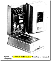
A manual motor starter rated in horsepower provide reliable control and overload protection for motors up t1 about 5 hp single phase, and 10 hp 3 phase, Figure 17 3 A thermally activated trip mechanism opens the mote circuit automatically if an overload occurs. The overloa heaters are sized based upon the full load current ratin of the motor. Manual motor starters are available fc both single and 3 phase motors.
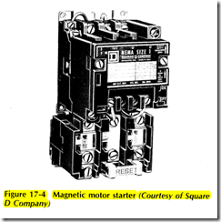
Magnetic motor starters use an electric solenoid co to close the contacts and start the motor, Figure 17 ~ These motor starters may be operated by a person actt ally activating a starting control, or they may be operate automatically. Only the magnetic motor starter can b controlled automatically. Magnetic motor starters ca operate motors of up to several hundred horsepowe
Thermally activated overload relays break the circuit to the coil of the starter if a motor overload occurs. The overload heaters are sized for the nameplate full load current of the motor


