Single-phase pulse width modulation (PWM) inverter
The fact that the voltage supply to the stator, of an AC induction motor, is a square wave and is not distorted in itself is a problem to the motor. The main problem comes from the distortion of the current waveform, which results in extra copper losses and is due to shaft torque pulsations. The ideal inverter output is one, which results in a current waveform of low harmonic distortion.
An AC induction motor is predominantly inductive, with a reactance that depends on the frequency (XL = j2πfL). It is, therefore, beneficial if the voltage harmonic distortion can be pushed into high frequencies, where the motor impedance is high and not much distorted current will flow.
One technique for achieving this is the sine-coded pulse width modulation (sine-PWM). This requires the power devices to be switched, at frequencies much greater than that of the fundamental frequency, producing a number of pulses, for each portion of the desired output period. The frequency of the pulses is called modulation frequency.
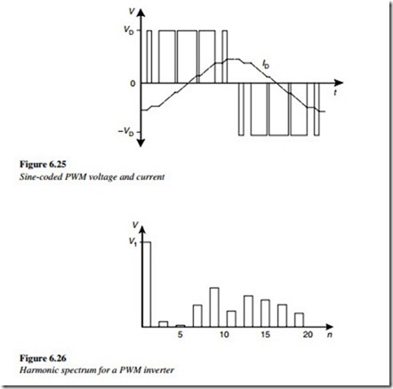
The width of the pulses is varied throughout the cycle in a sinusoidal manner, giving a voltage waveform as shown in Figure 6.25. The figure also shows the current waveform for an inductive load, by showing the improvement in a waveform.
The improvement in the current waveform can be explained by the harmonic spectrum shown in Figure 6.26. It can be seen that, although the voltage waveform still has many distortion components, they now occur at higher harmonic frequencies, where the high- load impedance of the motor is effective in reducing these currents.
Increasing the modulation frequency will improve the current waveform, but at the expense of increased losses in the switching devices of the inverter. The choice of modulation frequency depends on the type of switching device and its frequency. With the force-commutated thyristor inverter, a modulation frequency of up to 1 kHz was possible with the older technologies.
With the introduction of GTOs and BJTs, this could be pushed up to around 5 kHz. With IGBTs, the modulation frequency could be as high as 20 kHz.
In practice, a maximum modulation frequency of up to 12 kHz is common with IGBT inverters up to about the 22 kW motor size and 8 kHz for motors up to about 500 kW. The choice of modulation frequency is a trade-off, between the losses in the motor and in the inverter. At low-modulation frequencies, the losses in the inverter are low and those in the motor are high. At high-modulation frequencies, the losses in the inverter increase, while those in the motor decrease.
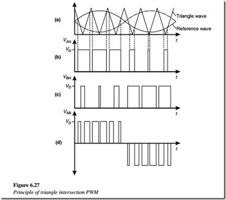
One of the most common techniques for achieving the sine-coded PWM in practical inverters is the sine–triangle intersection method shown in Figure 6.27. A triangular saw- tooth waveform is produced in the control circuit at the desired inverter-switching frequency. This is compared in a comparator, with a sinusoidal reference signal, which is equal in frequency and proportional in magnitude to that of the desired sinusoidal output voltage. The voltage VAN (Figure 6.27(b)) is switched high whenever the reference waveform is greater than the triangle waveform. The voltage VBN (Figure 6.27(c)) is not controlled by the same triangle waveform but with a reference waveform shifted by 180º.
The actual phase-to-phase output voltage is then VAB (Figure 6.27(d)), which is the difference between VAN and VBN, which consists of a series of pulses, each of whose width is related to the value of the reference sine wave at that time.
The number of pulses in the output voltage VAB is double that in the inverter leg voltage VAN. For example, an inverter switching at 5 kHz should produce a switching distortion at 10 kHz in the output phase-to-phase voltage. The polarity of the voltage is alternatively positive and negative at the desired output frequency.
It can also be seen that the reference sine wave in Figure 6.27 is given a DC component so that the pulse produced by this technique has a positive width. This puts a DC bias on the voltage of each leg as shown in Figures 6.2(b) and (c). However, each leg has the same DC offset which disappears from the load voltage.
The technique of using a sine-triangle intersection is particularly suited to the old analog control circuits, where the two reference waveforms are fed into a comparator and the output of the comparator is used to trigger the inverter switches. Modern digital techniques operate based on a switching algorithm. For example, by producing triggering pulses proportional to the area under a part of the sine wave.
Recently, manufacturers have developed a number of different algorithms that optimize the performance of the output waveforms for AC induction motors. These techniques result in PWM output waveforms, which are similar to those shown in Figure 6.27. The sine-coded PWM voltage waveform is a composite of a high-frequency square wave at the pulse frequency (the switching carrier) and the sinusoidal variation of its width (the modulating waveform). It has been found that, for the lowest harmonic distortion, the modulating waveform should be synchronized with the carrier frequency, so it contains an integral number of carrier periods.
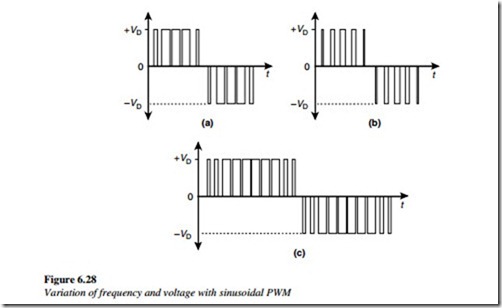
This requirement becomes less important with high carrier frequencies of more than twenty times the modulating frequency. The voltage and frequency of a sinusoidal PWM waveform are varied by changing the reference waveform of Figure 6.27(a), giving outputs as shown in Figure 6.28.
Figure 6.28(a) shows a base case, with the rated V/f ratio. Figure 6.28(b) shows the case where the voltage reference is halved, resulting in the halving of each pulse. Figure 6.28(c) shows the case where the reference frequency is halved, resulting in the extension of the modulation over twice as many pulses.
The largest voltage with the sine-coded PWM occurs when the pulses in the middle are the widest, giving an output with a peak voltage equal to the supply.
Modulation index
This is defined as the ratio of the peak AC output to the DC supply. Thus, the largest output voltage occurs when the modulation index is 1.
It is possible to achieve a high value of modulation index by abandoning the strict sine- PWM and by adding some distortion to the sinusoidal reference voltage. This results in the removal of some of the pulses near the center of the positive and negative parts of the waveform. This is a process called pulse dropping. In the limit, a square voltage waveform can be achieved with a modulation index of 1.


