Plug stop and anti-plug circuits
To halt a motor or to stop a running motor, a common method is to remove the supply voltage and allow the motor and load to come to a stop.
Nevertheless, in some applications, the motor must be stopped instantaneously or held in position by some sort of a braking device.
This is achieved using the electric braking circuit. It uses the windings of the motor to produce a retarding torque. The kinetic energy of the rotor and the load is dissipated as heat in the rotor bars of the motor.
The following are the two different means of electric braking:
1. Plugging
2. Dynamic braking.
Plugging
In this method, a motor is connected to run in a reverse direction. This is done while the motor is still running in a forward direction, resulting in motor stoppage.
In order to achieve this, a switch, or a contact is used which gives the status of the motor. Depending on the running of a motor and its speed, the switch status changes from NO to NC.
This switch is called the zero-speed switch or the plugging switch. A zero-speed switch prevents a motor from reversing after it has come to a stop.
A ‘zero-speed’ switch is physically coupled to a moving shaft on the machinery, the motor of which is to be plugged. As the zero-speed switch rotates along with the machine, the centrifugal force causes the contacts of the switch to open or close, depending on its intended use.
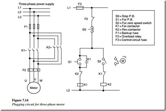
Each zero-speed switch has a rated operating speed range, within which the contacts will be switched, example, 10–100 rpm. The control schematic of Figure 7.14 shows one method of plugging a motor to stop from one direction only.
As the start (forward) pushbutton is pressed, it energizes forward the contactor coil K1. Therefore, the motor runs in the forward direction. The contactor K1 is latched through its latching contact.
As the motor runs in the forward direction, the NC contact F (zero switch) opens the circuit of the reverse contactor coil K2. If the stop pushbutton is pressed, it will de-energize the forward contactor K1. This in turn will help the reverse contactor K2 to energize because the forward contact on the speed switch is also in a closed condition.
As the reverse contactor is energized, the motor is plugged. The motor starts decreasing in speed rapidly up to the setting of the speed switch, at which point its contact opens and de-energizes the reverse contactor K2.
This contactor is used, only to stop the motor, using the plugging operation. It is not used to run the motor in reverse. Many machines require the motor be able to reverse. Most small machines are not adversely affected by reversing the motor, before coming to a stop.
This is not true of larger pieces of equipment. The sudden reversing torque applied when a large motor is reversed (without slowing the motor speed) could damage the motor.
The driven machinery and the extremely high current could affect the distribution system. Plugging a motor for more than five times a minute requires the motor starter to rated.
Anti-plugging
be de-
Anti-plugging protection is necessary, when a motor with large inertia is connected suddenly, in a reverse direction, while the motor is still running in a forward direction.
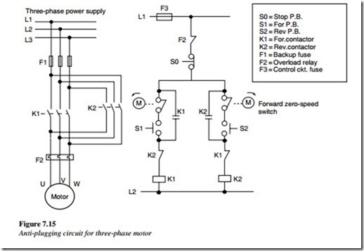
Anti-plugging protection prevents the application of a counter torque, until the motor speed is reduced to an acceptable value. In the anti-plugging circuit shown in Figure 7.15,
the motor can be reversed but not plugged. Pressing the forward pushbutton completes the circuit for the K1 contactor coil causing the motor to run in the forward direction. It continues to run because of the latching contacts of K1. With the NC contact F (zero- speed switch contact) in reverse, the contactor K2 opens, because of the forward rotation of the motor.
Pressing the stop button de-energizes the K1 contactor coil, which opens the latching contact of K1 also, causing the motor to slow. Pressing the reverse button will not complete a circuit for the K2 contactor coil until the F (zero-speed switch) contact re-closes (i.e., when the speed is reduced below switch setting).
Therefore, only when the motor reaches a near-zero speed, can the reverse circuit be energized. The motor now runs in a reverse direction.

