Using PRINTERS for diagnostics
One of the major limitations of printer troubleshooting has been testing. Traditionally, a technician was limited to the “self test” of each unique printer, or printing simple documents from a text ed itor or other basic application. There are two problems with this haphazard approach. First, self-tests and simple printouts do not always test every feature of the printer in a clear fashion. Second, such testing is hardly ever uniiorm; the quality and range of test ing can vary radically from printer to printer. Dynamic Learning Systems has addressed this problem by developing PRINTERS , which is a PC-based utility designed to provide you with a suite of standardized printer tests. This chapter introduces you to PRINT ERS. It details how to get your own copy of PRINTERS , how to in stall it on your PC, and how to use it produ ctively in a matter of minutes.
Before going any further, you should understand that you do not have to purchase PRINTERS to troubleshoot your printer effec tively; that would certainly not be fair to you. The majority of this book is written without relying on the use of a companion disk. However, PRINTERS provid es you with a reliable platform for test ing dot-matrix, ink jet, and EP printers. PRINTERS not only exer cises a printer’s main functions (e.g., carriage, line feed, print head , and so on), but it also allows you to test printer-specific functions through the use of escape sequences. You will fmd PRINTERS to be an inexpensive but handy addition to your toolbox.
All about PRINTERS
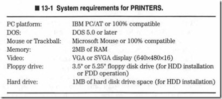
PRINTERS is a stand-alone DOS utility designed to drive virtually any commercial impact, ink jet, and Laser/LE D (EP) printer through a series of exercises and test patterns specially tailored to reveal faults in the printer’s major subassemblies. By reviewing the printed results, you will be able to estimate the source of a printer’s problems with a high degree of confidence. On-line help and tutorial modes provide additional information about each test, and help you to understand the printed results. A variety of op tions allow you configure PRINTERS for over 220 unique printers, and tailor performance for speed and print quality. A handy “Man ual Code” section allows you to enter Escape Code Sequences and text that can test specific functions of any printer. The system re quirements for PRINTERS is shown in Table 13-1.
13–1 System requirements for PRINTERS.
Obtaining your copy of PRINTERS
You can buy a copy of PRINTERS directly from Dynamic Learning Systems. An advertisement and order form are included at the end of this book. Feel free to photocopy the order form (or tear out the page), and fill out the requested information carefully. Please re member that all purchases must be made in United States funds. When you fill out the order form, you can select the companion disk alone, a one-year subscription to the premier newsletter The PC Toolbox, or take advantage of a very special rate for the disk and subscription. Subscribers also receive extended access to the Dynamic Learning Systems BBS that allows you to exchange e-mail with other PC enthusiasts, and download hundreds of DOS and Wmdows PC utilities. Be sure to specify your desired disk size (3.5″ or 5.25″).
Installing & starting from the floppy drive
Your first task should be to make a backup copy of PRINTERS on a blank floppy disk. You can use the DOS DISKCOPY function to make your backup. For example, the command line:
C:\> diskcopy a: a: <ENTER>
will copy the original disk. Keep in mind that you will have to do a bit of disk swapping with this command. Ifyou wish to use a floppy drive besides A:, you should substitute the corresponding letter for that drive. Ifyou are uncomfortable with the DISKCOPY command, refer to your DOS manual for additional information. PRINTER S is designed to be run directly from the floppy disk, so you can keep the original disk locked away while you run from the copy. This al lows you to take the disk from machine to machine so that you will not clutter your hard drive, or violate the licensee agreement by loading the software onto more than one machine simultaneously.
The following instru ctions will help you through the process:
1. To start PRINTERS from the floppy drive, insert the floppy into the drive and type the letter of that drive at the command prompt and press enter. The new drive letter should now be visible . For example, you can switch to the A: drive by typing:
C:\> a: <ENTER>
the system will respond with the new drive letter:
A:\>_
2. Then, type the name of the executable file:
A:\> printers <ENTER>
3. If you are using a floppy drive other than A:, you should substitute that drive letter (such as B:) in place of the A:. PRINTERS will start in a few moments and you will see the title screen and disclaimer. Press any key to pass the title screen and disclaimer, and you will then see the main menu.
Installing & starting from the hard drive
If you will only be using one PC and you have an extra 1.0MB or so, you should still go ahead and make a backup copy of the PRINTERS disk as described in the previou s section, but it would probably be more convenient to install the utilities to your hard drive. There is no automated installation procedure to do this, but the steps are very straightforward:
1. Boot your PC from the hard drive and when you see the command prompt , switch to the root directory by typing the cd\ command :
C:\> cd\ <ENTER>
the system should respond with the root comm and prompt:
C :\)_
2. Use the DOS md comman d to create a new subdirectory that will contain the companion disk’s flies. One suggestion is to use the name PRINTERS such as:
C :\> md printers <ENTER>
3. Switch to the new subdirectory using the cd\ command:
C:\> cd\printers <ENTER>
The system should respond with the new subdirectory label such as:
C:\PRINTERS>_
You might of course use any DOS-valid name for the subdirectory, or nest the directory under other directmies if you wish. If you are working with a hard drive other than C:, substitute that drive label for C:.
4. Insert the backup floppy disk into the floppy drive. Use the DOS COPY command to copy all of the floppy disk files to the hard drive such as:
C:\PRINTERS> copy a:*.* c: <ENTER>
This instructs the system to copy all files from the A: drive to the CUITent directory of the C: drive. Because PRINTERS is not distributed in compr essed form, uncompressing (or unzipping) is not needed.
5. After all files have been copied, remove the floppy disk and store it in a safe place. Then, type the name of the utility you wish to use such as:
C :\> printers <ENTER>
The title screen and disclaimer for PRINTERS should appear almost immediately. Press any key to pass the title screen and disclaimer, and you will then see the main menu.
The work screen
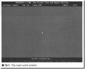
After you pass the title screen and disclaimer, you will see the work screen, as illustrated in figure 13-1. The top of the work screen contain s the title bar and main m enu bar. The bottom of the work screen contains the message bar and copyright bar. Most of the work screen is empty now. There are six entries in the main menu bar; these are the essential areas that you will be concerned with while using PRINTERS.
– Configure Allows you to select the program’s operating parameters.
– Impact Allows you to run a selection of tests for Impact printers.
– Ink Jet Allows you to run a selection of tests for Ink Jet printers.
– Laser/LED Allows you to run a selection of tests for EP printers.
– About Shows you more information about PRINTERS .
– Quit Leaves PRINTERS and returns to DOS
Configuring the program
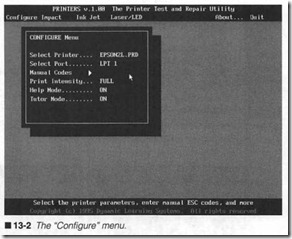
To configure the various options available in PRINTERS, click on “Configure” in the main menu bar (or press C). The CONFIGURE menu will appear, as shown in figure 13-2. You can return to the work screen at any time by pressing the <ESC> key or right click ing anywhere in the display.
Select printer
PRINTERS is compatible with the vast majority of Epson and Hewlett-Packard compatible printers now in the mark et, but the utility provides an extensive library of over 220 specific printer drivers. These drivers allow PRINTERS to produce the detailed graphic test patterns used in the program. Table 13-2 shows a comprehensive listing of supported printers and their correspond ing driver entries. By default, PRINTERS is set to use the EP SON2L.DRV driver (a generic Epson 24-pin impact printer driver). Refer to Table 13-2 to select the appropriate driver, then scroll through the available printer drivers by left clicking on “Se lect Printer” (or press “p”). As you scroll through each driver, you can see details about each driver in the message bar.
Hidden key alert: If you accidentally pass the desired driver, you can scroll backward through the driver list by pressing “SHIFT” and “p” simultaneously (capitol “P”).
Select port
PRINTERS is designed to operate a printer on LPTl ough LPT3, or COMl or COM2. Left click on “Select Port” (or pres ‘r”) to scroll through available ports. Remember to connect your printer to the appropriate port before proceeding. By default, LPT1 is the selected port.
Manual codes
Most print ers provide a suite of plinter-speci.fic functions and fea tures (e.g., bold print, underlining , double-width prin t, double height print , and so on). While it would be virtually impossible for any diagnostic to test each of these functions for every available printer, PRINTERS provides a means for you to test your printer’s functions manually using printer codes (also referred to as Escape Sequences or Escape Codes). The Manual Codes feature provid es a printer technician with almost unlimited versatility in checking and verifying the most subtle features of a printer’s operation.
Information alert: In order to enter an Escape Code, you will need the User’s Manual for your particular printer. The diskette’s docu mentation lists Escape Codes for several popular printer models, but to test printer-specific functions, you will need printer-specific documentation.
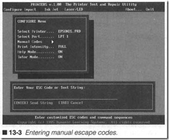
To enter an Escape Code, left click on “Manual Codes” (or press “C”) in the CONFIGURE menu. A text entry window will appear below the CONFIGURE menu, as in figure 13-3. You might enter up to 50 characters per line. Pressing the <TAB> key or right clicking anywhere on the display will abort the text entry routine. If you make a mistake in typing, simply backspace past the error and correct the mistake.
Example 1: Setting the Panasonic KX–P1124 to Underline mode
With the text entry routine running , reset the printer (by turning it off and on), then enter the following text, then press <ENTER>:
This is a test of default text
Your printer should print this text string in its default font and pitch. Now let’s set the printer to its underline mode using the code ESC – 1 (from the PRINTERS documentation). Type the three keystrokes and press <ENTER>. Keep in mind that when
you press the <ESC> key, a backspace arrow will appear in that space:
<ESC> -1
The printer should now be in underline mode, so type the follow ing text and press <ENTER>
This is the printer’s underline mode
The printer should produce this text underlined. To turn the un derline mode off, enter the code ESC – 0 (from PRINTER S docu mentation). Type the three keystrokes and press <ENTER>. Keep in mind that when you press the <ESC> key, a backspace arrow will appear in that space:
<ESC>-0
Now type the following text and press <ENTER>:
The underline mode is off
The type should no longer be underlined. To leave the text entry
routine, press <TAB> or right click anywhere on the display.
Example 2: Setting the Panasonic KX-P1124 to Letter Quality (LQ) mode
With the text entry rou tine running, reset the printer (by turning
it off and on) , then enter the following text, then press <ENTER>:
This is the printer ‘s default text
Your printer should print this text string in its default font and pitch. Now let’s set the printer to its LQ mode using the code ESC x 1 (from PRINTERS documentation). Type the three keystrokes and press <ENTER>. Keep in mind that when you press the
<ESC> key, a backspace arrow will appear in that space:
<ESC>xl
The printer should now be in letter quality mode, so type the following text and press <ENTER>:
This is the printer’s LO mode
The printer should produce this text in higher quality than the de fault. To turn the LQ mode off, enter the code ESC x 0 (from PRINTERS documentation). Type the three keystrokes and press
<ENTER>. Keep in mind that when you press the <ESC> key, a backspace arrow will appear in that space:
<ESC>xO
Now type the following text and press <ENTER>:
The letter quality mode is off
The type should be back in its draft form. To leave the text entry routine, press <TAB> or right click anywhere on the display.
Print intensity
The print intensity setting allows you to set the overall darkness and lightness (i.e., contrast) of your test images. There are two choices: half and full. By default, all images are printed at full in tensity (maximum contrast). At half intensity, the shading is light ened to reduce the image’s contrast. You can toggle between full and half intensity by clicking on “Print Intensity” (or pressing “I”). For low-resolution devices (impact printers at 75 dpi or less) , full intensity will typically yield superior results. For medium-to-high resolution devices (ink jet and almost all EP printers), half inten sity is often better. Of course, you might experiment to find the best settings for your particular printer.
Help mode
PRINTERS is designed with two on-line documentation sources that are intended to provid e instruction and guidance before and after a test is conducted. The help screens appear before the selected test starts, and will give insights into the purpose and ob jectives of the selected test. You might toggle the help mode on or off by left clicking on “Help Mode” (or pressing “H”). By default, the help mode is on. If you turn the help mode off, the selected test will start immediately.
Tutor mode
PRINTERS is designed with two on-line documentation sources that are intended to provide instruction and guidance before and after a test is conducted. The tutor screens appear after the se lected test is complete, and will give advice on how to interpret the printed results. You can toggle the tutor mode on or off by left clicking on “Tutor Mode” (or pressing “T”). By default, the tutor mode is on. If you turn the tutor mode off, there will be no in struction provided when the test is finished.
Running the impact tests
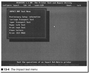
The impact tests allow you to check the operations of almost any impact dot-matrix printer (and any 9-pin or 24-pin printer capable of Epson emulation). From the main menu bar, left click on “Im pact” (or press “I”). The IMPACT DMP Test Menu will appear, as shown in figure 13-4. You can return to the main menu at any time by pressing the <ESC> key or right clicking anywhere in the dis play. There are seven functions available from the IMPACT DMP test menu:
0 Preliminary Setup Information Supplies initial information to help you set up and operate the printer safely.
0 Carriage Transport Test Allows you to test the Impact DMP carriage transport system.
0 Paper Transport Test Allows you to test the Impact DMP paper transport system.
0 Paper Walk Test Allows you to check friction feed paper transport systems in Impact DMPs.
0 Print Head Test Allows you to test the Impact DMP print head assembly.
0 Clean Rollers Allows you to check and clean the paper handling rollers.
0 Print TEST PAGE Provides a uniform test pattern for initial or final printer inspection.
Preliminary Setup Information
You can access the preliminary setup information screen by left clicking on “Preliminary Setup Information” (or press “1”). This is not a test per se, but an inf01mation screen intended to provid e helpful setup information. Novice troubleshooters will find it help ful to review this information before attempting any of the test se quences below. Experienced troubleshooters might find this to be a handy reminder. To leave the information screen, press <ESC> or right click anywhere in the display.
Carriage Transport Test
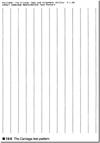
Impact printers are moving carriage devices; that is, the print head is carried left and right across the page surface. This movement is handled by the carriage transport mechani sm. Proper printing of text and graphics demands that the print head be positioned pre cisely in both its left-to-right and right-to-left movement. The Car riage Transport Test is designed to test carriage alignment by generating a series of vertical lines, as shown in figure 13-5. The print head sweeps from left-to-right producing a series of vertical tic marks, then reverses direction and produces a right-to-left se ries of tic marks . Similarly, each line of tic marks is the result of two independent passes. Using this approach, we can check car riage alignment not just between lines, but within the same line.
If the tic marks are not aligned precisely, there might be some me chanical slop in the carriage mechanics. Badly or erratically placed tic marks might indicate a fault in the carriage motor driver cir cuitry, or in the carriage home sensor. If marks within the same line are aligned precisely at the edges (but not elsewhere in the line), there might be wiring problems in the print head or print head cable. You might start this test by left clicking on “Carriage Transport Test” (or press “C”).
Paper Transport Test
There are two traditional means of moving paper through a printer: pull the paper (with a tractor feed), or push the paper (with a friction feed). Regardless of the means used, paper must be carried through a printer evenly and consistently; otherwise, print will overlap and cause distortion. The Paper Transport Test is designed to check the paper transport system’s operation. The Paper Transport Test works with any transport type; however, it is intended prin\arily for tractor feed systems that pull the paper through. The test pattern counts off a number of marked passes. You must check each pass to see that they are spaced evenly apart. Ifnot, there might be a problem with the transport mechanics, mo tor, or driving circuitry. To start this test, left click on “Paper Transport Test” (or press “P”).
Paper Walk Test
Like the last test, the Paper Walk Test is designed to check the pa per transport system’s operation. While the Paper Transport Test is best utilized with tractor feed paper transports, the Paper Walk Test is intended primarily for friction feed systems, which push the paper through. The test pattern generates a series of evenly spaced horizontal lines. You must check each pass to see that they are spaced evenly apart. If not, there might be a problem with the transport mechanics, motor, or driving circuitry.
Another problem particular to friction feed paper transports is the tendency to “walk the page.” Proper friction feed operation de pends on roller pressure applied evenly across the entire page sur face. Any damage, obstructions, or wear could cause excessive roller pressure that can allow the page to spin clockwise or coun terclockwise. If you notice lines closer together on the left or right side of the image, the roller assembly might need adjustment or replacement, or there might be an obstruction in the paper path. To start this test, left click on “Paper Walk Test” (or press “W”).
Print Head Test
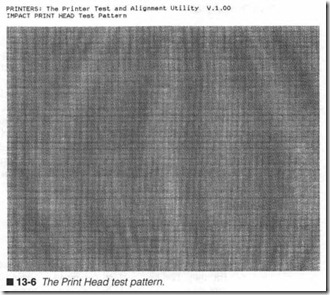
Ideally, every pin on the print head should flre reliably. In actual practice, however, age, lack of routine maintenance, and heat buildup can affect firing reliability. This often results in horizontal white lines in the text where the corresponding print wires fail. The best way to stress-test an impact print head and detect prob lems is by printing a dense graphic. The impact print head test produces a large black rectangle, as shown in figure 13-6; this de mands the proper operation of all print wires, and will often reveal
any age, damage, or heat and maintenance-related issues. You can adjust the speed and density of printing by adjusting print intensity and driver resolution under the CONFIGURE menu.
Examine the black rectangle for horizontal white lines. Consistent white lines indicate that a print wire is not firing. Check and clean the face of the print head to remove any accumulations of debris that might be jamming the print wire(s). If the problem persists , there might be a fault in the print head or print wire driver cir cuitry. If white lines appear only briefly or intermittently, there might be wiring problems with the print head cable, or within the print head itself. There might also be an intermittent problem in the corresponding print wire driver circuit. Finally, print intensity should be relatively consistent throughout each pass. Light (or jaded) printing might indicate trouble with print head wear or spacing, ribbon quality, or the power supply. To start this test, left click on “Print Head Test” (or press “H”).
Clean Rollers
To combat the dust and debris that naturally accumulate in the printer’s mechanics, it is customary to periodically clean the main rollers that handle paper, usually the platen and other major rollers. This is especially important for friction feed paper trans ports where age and any foreign matter on the rollers can interfere with the paper path and “walk” the page. While it is possible (and sometimes more convenient) to rotate the rollers by hand (using the platen knob), the Clean Rollers function provides a paper ad vance that allows you to streamline the routine cleaning/rejuvena tion of roller assemblies. Paper must be present in the printer to use this function.
The typical cleaning procedure involves rotating the rollers while wiping them gently with a clean cloth lightly dampened with wa ter. You might use a bit of very mild household detergent to re move grime that resists water alone, but avoid using detergent regularly because chemicals applied to rubber and other synthetic roller materials can reduce their pliability. Never use harsh deter gents or solvents! If you choose to try rejuvenating the rollers with a roller cleaning solvent, use extreme caution. First, work in a ven tilated area (solvent fumes are dangerous). Second, it is impossi ble to predict how cleaning solvents will affect every possible roller material, so always try the solvent on a small edge patch of the roller in advance. To start this procedure, left click on “Clean Rollers” (or press “R”). A single cycle will advance the paper transport by two pages.
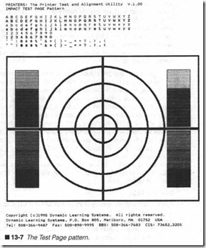
Print TEST PAGE
The TEST PAGE is typically the first and last test to be run on any printer. Initially, the test page will reveal problems with the print head, paper transport, or carriage transport. You can then proceed with more detailed tests to further isolate and correct the prob lem(s). When the repair is complete, the TEST PAGE is proof of the printer’s operation, which you can keep for your records, or provide to your customer. The moving-head TEST PAGE pattern is illustrated in figure 13-7. To start this test, left click on “Print TEST PAGE” (or press “T”).
Running the ink jet tests
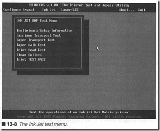
The ink jet tests allow you to check the operations of almost any ink jet dot-matrix printer (and any printer capable of HP DeskJet emulation). From the main menu bar, left click on “Ink Jet” (or press “J”). The INK JET DMP Test Menu will appear, as shown in figure 13-8. You can return to the main menu at any time by pressing the <ESC> key or right clicking anywhere in the display. There are seven functions available from the INK JET DMP test menu:
0 Preliminary Setup Information Supplies initial information to help you set up and operate the ink jet printer safely.
0 Carriage Transport Test Allows you to test the Ink Jet DMP carriage transport system.
0 Paper Transport Test Allows you to test the Ink Jet DMP paper transport system.
0 Paper Walk Test Allows you to check friction feed paper transport systems in Ink Jet DMPs.
0 Print Head Test Allows you to test the Ink Jet DMP print head assembly.
0 Clean Rollers Allows you to check and clean the paper handling rollers.
0 Print TEST PAGE Provides a uniform test pattern for initial or final printer inspection.
Preliminary Setup Information
You can access the preliminary setup information screen by left clicking on “Preliminary Setup Information” (or press”!”). This is not a test per se, but an information screen intended to provid e helpful setup information. Novice troubleshooters will find it help ful to review this information before attempting any of the ink jet test sequences below. Experienced troubleshooters might find this to be a handy reminder. To leave the information screen, press <ESC> or right click anywhere in the display.
Carriage Transport Test
Like impact print ers, ink j et printers are movin g-carriage devices; that is, the print head is carried left and right across the page sur face. This movement is handled by the carriage transport mecha nism. Proper printing of text and graphics demands that the print head be positioned precisely in both its left-to-right and right-to left movement. The Carriage Transport Test is designed to test carriage alignment by generating a series of vertical lines (similar to figure 13-5). The print head sweeps from left to right producing a series of vertical tic marks, then it reverses direction and pro duces a right-to-left series of tic marks. Similarly, each line of tic marks is the result of two independent passes. Using this ap proach, we can check carriage alignment not just between lines, but within the same line.
If the tic marks are not aligned precisely, there might be some me chanical slop in the carriage mechanics. Badly or erratically placed tic marks might indicate a fault in the carriage motor driver cir cuitry, the mechanical home sensor, or the optical position en coder. If marks within the same line are aligned precisely at the edges (but not elsewhere in the line), there might be wiring prob lems in the ink jet print cartridge or print head cable. To start this test, left click on “Carriage Transport Test” (or press “C”).
Paper Transport Test
There are two traditional means of moving paper through a printer: pull the paper (with a tractor feed), or push the paper (with a friction feed). Regardless of the means used, paper must be carried through a printer evenly and consistently; otherwise, print will overlap and cause distortion. The Paper Transport Test
is designed to check the paper transport system’s operation. While the Paper Transport Test will work with any transport type, it is intended primarily for tractor feed systems, which pull the paper through. The test pattern counts off a number of marked passes. You must check each pass to see that they are spaced evenly apart. If not, there might be a problem with the transport mechanics, mo tor, or driving circuitry. To start this test, left click on “Paper Transport Test” (or press “P”).
Paper Walk Test
Like the last test, the Paper Walk Test is designed to check the pa per transport system’s operation. While the Paper Transport Test is best utilized with tractor feed paper transports, the Paper Walk Test is intended primarily for friction feed systems, which push the paper through. Today’s ink jet printers utilize friction feed sys tems almost entirely. The test pattern generates a series of evenly spaced horizontal lines. You must check each pass to see that they are spaced evenly apart. If not, there might be a problem with the transport mechanics, motor, or driving circuitry.
Another problem particular to friction feed paper transports is the tendency to “walk the page.” Proper friction feed operation de pends on roller pressure applied evenly across the entire page surface. Any damage, obstructions, or wear might cause excessive roller pressure that can allow the page to spin clockwise or coun terclockwise. This is especially evident in inexpensive ink jet sys tems. If you notice lines closer together on the left or right side of the image, the roller assembly might need adjustment or replace ment, or there might be an obstruction in the paper path. To start this test, left click on “Paper Walk Test” (or press “W”).
Print Head Test
Ideally, every nozzle on the ink cartridge should fire reliably. In ac tual practice, however, cartridge age, lack of routine maintenance, low ink levels, and circuit defects can affect firing reliability. This often results in horizontal white lines in the text where the corre sponding print nozzles fail. The best way to stress-test an ink jet print head and detect problems is by printing a dense graphic. The ink jet print head test produces a large black rectangle (similar to figure 13-6); this demands the proper operation of all print noz zles, and will often reveal any age, damage, or maintenance related issues. You can adjust the speed and density of printing by adjusting print intensity and driver resolution under the CONFIG URE menu. Remember that this is a very dark image that will re quire a substantial amount of ink to form. If the current ink. cartridge is marginal, you might need to install a new ink cartridge before proceeding.
Examine the black rectangle for horizontal white lines. Consistent white lines indicate that a print nozzle is not firing. Check and clean the face of the print cartridge to remove any accumulations of dried ink or debris that might be jamming the print nozzle(s).lf the problem persists, there might be a fault in the print cartridge or print nozzle driver circuitry. If white lines appear only briefly or intermittently, there might be wiring problems with the print head cable, or within the print cartridge itself. There might also be an intermittent problem in the corresponding print nozzle driver cir cuit. Finally, print intensity should be relatively consistent throughout each pass. Light (or jaded) printing might indicate poor paper selection, low ink levels, or trouble with the print noz zle power supply. To start this test, left click on “Print Head Test” (or press “H”).
Clean Rollers
To combat the dust and debris that naturally accumulate in the printer’s mechanics, it is customary to periodically clean the main rollers that handle paper, usually the platen and other major rollers. This is especially important for delicate ink jet friction feed paper transports where age and any foreign matter on the rollers can interfere with the paper path and “walk” the page. Few con temporary ink jet designs allow you to rotate the rollers by hand (using a platen knob), so the Clean Rollers function provides a pa per advance that allows you to streamline the routine cleaning/re juvenation of roller assemblies. Paper must be present in the printer to use this function.
The typical cleaning procedure involves rotating the rollers while wiping them gently with a clean cloth lightly dampened with wa ter. You might use a bit of very mild household detergent to re move grime that resists water alone, but avoid using detergent regularly because chemicals applied to rubber and other synthetic roller materials can reduce their pliability. Never use harsh deter gents or solvents! If you choose to try rejuvenating the rollers with a roller cleaning solvent, use extreme caution. First, work in a ven tilated area (solvent fumes are dangerous). Second, it is impossi ble to predict how cleaning solvents will affect every possible roller material, so always try the solvent on a small edge patch of the roller in advance. To start this procedure, left click on “Clean Rollers” (or press “R”). A single cycle will advance the paper transport by two pages.
Print TEST PAGE
The TEST PAGE (such as the one shown in figure 13-7) is typi cally the first and last test to be run on any printer. Initially, the test page will reveal problems with the print cartridge, paper transport, or carriage transport. You can then proceed with more detailed tests to further isolate and correct the problem(s). When the repair is complete, the TEST PAGE is proof of the printer’s op eration, which you can keep for your records, or provide to your customer. To start this test, left click on “Print TEST PAGE” (or press “T”).
Running the Laser/LED tests
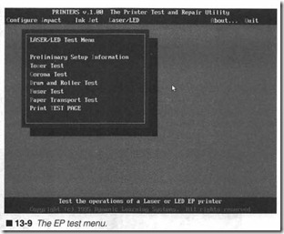
The Laser/LED (EP) tests allow you to check the operations of al most any electrophotographic (EP) printer (any printer capable of HP LaserJet emulation). From the main menu bar, left click on “Laser/LED” (or press “L”). The LASER/LED Test Menu will ap pear, as shown in figure 13-9. You can return to the main menu at any time by pressing the <ESC> key or right clicking anywhere in
the display. There are seven functions available from the INK JET
DMP test menu:
0 Preliminary Setup Information Supplies initial information to help you set up and operate the EP printer safely.
0 Toner Test Allows you to check the effects of low/expired toner or poor toner distribution.
0 Corona Test Allows you to quickly identify the location of fouling on the Primary or Transfer corona wires.
0 Drum and Roller Test Allows you to identify the source of repetitive defects in the printer.
0 Fuser Test Allows you to check for low or inconsistent fusing.
0 Paper Transport Test Allows you to quickly and conveniently check the paper transport without wasting time or toner.
0 Print TEST PAGE Provides a uniform test pattern for initial or final printer inspection.
Preliminary Setup Information
You can access the preliminary setup information screen by left clicking on “Preliminary Setup Information” (or press “I”). This is not a test per se, but an information screen intended to provide helpful setup information for 8P testing. Novice troubleshooters will find it helpful to review this information before attempting any of the test sequences below. Experienced troubleshooters might find this to be a handy reminder. To leave the information screen , press <ESC> or right click anywhere in the display.
Toner Test
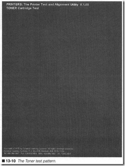
Toner is the raw material (the media) that is used to form printed images (the “ink” of the EP printer). As a consequence, low, ex pired, poor-quality , or badly distributed toner will have an impact on print quality. The Toner Test is designed to test toner condition by printing a full-page black graphic, as shown in figure 13-10.
Light streaks appearing vertically along the page (usually on ei ther side of the image) are typical of a low-toner cartridge. An overall light image might be compensated for by increasing the print intensity wheel (on the printer itself), but it might also sug gest a poor-quality toner cartridge or expired toner. If a fresh toner cartridge fails to correct the problem and print intensity is already set high, the fault might be in the printer’s high-voltage power supply. Remember that EP printing technology is heavily dependent on paper type and quality. Light splotches might be the result of damp or coated paper. Try a supply of fresh, dry 20-lb. xe rography-grade paper. To start this test, left click on “Toner Test” (or press “n”).
Corona Test
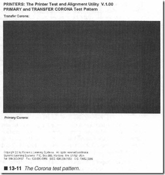
EP technology relies on high voltage to produce the electrostatic fields that charge the EP drum, and attract toner off the drum to the page. These fields are established by a Primary corona and a 1Tansfer corona respectively. A corona is really nothing more than a length of thin wire, but it has a critical impact on the evenness of the electric field it produces. Later EP engines replace corona wires with charge rollers, but the effect is the same as corona wires. The Corona Test pattern shown in figure 13-11 is designed to highlight corona problems.
The dust and paper particles in the air tend to be attracted to high voltage sources, such as corona wires. Over time, an accumulation of foreign matter will weaken the field distribution and affect the resulting image. Fouling at one or more points on the primary corona will cause toner to always be attracted to those corre sponding points on the drum; this results in black vertical streaks that can be seen against a white background. Conversely, fouling at one or more points on the transfer corona will prevent toner at those corresponding points from being attracted off the drum and onto the page; this results in white vertical streaks that can be seen against a black background. To start this test, left click on “Corona Test” (or press “C”).
Drum and Roller Test
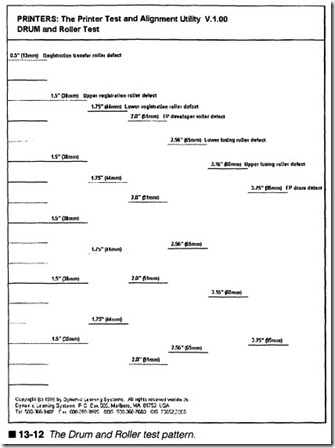
In spite of the high level of refinement in today’s EP printers, im age formation is still a delicate physical process. Paper must tra verse a torturous course through a series of roller assemblies in order to acquire a fmal, permanent image. With age, wear, and ac cidental damage, the various rotating elements of an EP printer can succumb to marks or other slight damage. While such damage is incidental, the results can be seen in the printed output.
Consider the EP drum itself. It has a circumference of about 3.75″. This means that any one point on the drum will approach every page surface at least twice. If a nick were to occur on the drum surface, it would appear in the final page at least twice, separated by about 3.75″. Because each of the major roller assemblies have a slightly different circumf erence, it is possible to quickly identify the source of a repetitive defect simply by measuring the clistance between instances. The Drum and Roller Test pattern shown in figure 13-12 is designed to help you correlate measured distances to problem areas. For example, a defect that occurs every 3.75″ can be traced to the EP drum , an error that occurs every 3″ or so can be traced to the fusing rollers, and a defect that occurs every 2″ can often be related to the development roller. To start this test, left click on “Drum and Roller Test” (or press “D”).
FuserTest
Fusing is a vital part of the image formation process; it uses heat and pressure to literally melt toner into the paper fibers. To ensure proper fusing, the upper fusing roller must reach and maintain a fairly narrow range of temperatures. When temperature is margin ally low, fusing might not be complete. The Fuser Test is intended to check the stability of a fusing system’s temperature control by running a series of full-page test graphics. You can then run your play.
thumb briskly over each page. Low or inadequate fusing will result in toner smudging (you can see toner on your thumb). You can then take the appropriate steps to optimize fusing temperature.
Note that this test is intended to detect marginal or inconsistent fusing performance; it will not catch a serious or complete fusing system failure because the printer will generate an error message and halt if the fusing assembly fails to reach proper fusing temper ature in 90 seconds or so, or falls below a minimum temperature for a prolonged amount of time. To start this test, left click on “Fuser Test” (or press “F”).
Paper Transport Test
The paper transport system of an EP printer is a highly modified friction feed system designed to carry paper through the entire image formation system. There are also a series of time-sensitive sensors intended to track each page as it passes (and detect jam conditions). When you work on any aspect of the printer’s me chanics, you are affecting paper transport. The Paper Transport Test is intended to eject five sheets of blank paper (saving toner and printing time). You can use this test to help you troubleshoot problems in the paper path, or verify that any repairs you might have made do not obstruct the paper path. Once a repair is com
plete, it is recommended that you verify the paper path before
running test patterns. To start this test, left click on “Paper Trans port Test” (or press “P”).
Print TEST PAGE
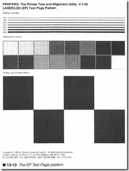
The TEST PAGE is typically the first and last test to be run on any Laser/LED printer. Initially, the Laser/LED test page (shown in fig ure 13-13) will reveal problems with the toner cartridge, paper transport, fusing system, coronas, or writing mechanism. You can then proceed with more detailed tests to further isolate and cor rect the problem(s). When the repair is complete, the TEST PAGE is proof of the printer’s operation, which you can keep for your records, or provide to your customer. To start this test, left click on “Print TEST PAGE” (or press “T”).
About PRINTERS
To learn about the PRINTERS program, click on “About” in the main menu bar (or press “A”). An information box will appear in the middle of the display. To clear the information box, press the
<ESC> key or click the right mouse button anywhere in the display .
Quitting PRINTERS
To quit the PRINTERS program and return to DOS, click on “Quit” in the main menu bar (or press “Q”). After a moment, the DOS prompt will appear.
Making PRINTERS better
Dynamic Learning Systems is dedicated to providing high-quality, low-cost diagnostic utilities. As a result, we are always interested in ways to improve the quality and performance of our products. We welcome your comments, questions, or criticisms: Dynamic Learning Systems
