 IMPEDANCE TRANSFORMATION THROUGH A TRANSFORMER
The impedance of a device is defined as the ratio of the phasor voltage across it to the phasor current flowing through it.
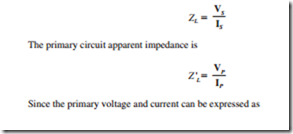
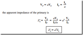
Since a transformer changes the current and voltage levels, it also changes the impedance of an element. The impedance of the load shown in Fig. 3.3b is
It is possible to match the magnitude of load impedance to a source impedance by simply selecting the proper turns ratio of a transformer.
Related posts:
Loudspeakers:Motional Impedance
POWER STATION PROTECTIVE SYSTEMS:DC TRIPPING SYSTEMS
Lamps and Light Fittings:Master Switching
TORQUE–SPEED CHARACTERISTICS – CONSTANT V/F OPERATION
Lighting Circuits:Sequence of Control
Video Synchronization:Persistence of Vision
PSYCHROMETRIC CHART FUNDAMENTALS:ASHRAE PSYCHROMETRIC CHARTS
Timing relays:Electronic Timers
Power and Energy:Work and Force
Electrical DC Servo Motors:Conclusion
Processing - Digital Electronics
Operation of the DC Welder Generator
Additional Information on Copper Wire
INDUSTRIAL COMPUTERS:INDUSTRIAL COMPUTER PERIPHERALS AND ACCESSORIES

