 ANALYSIS OF CIRCUITS CONTAINING IDEAL TRANSFORMERS
The easiest way to analyze a circuit containing an ideal transformer is by replacing the por- tion of the circuit on one side of the transformer by an equivalent circuit with the same ter- minal characteristics. After substitution of the equivalent circuit, the new circuit (without a
transformer present) can be solved for its voltages and currents. The process of replacing one side of a transformer by its equivalent at the second side’s voltage level is known as reflecting or referring the first side of the transformer to the second side.
The solution for circuits containing ideal transformers is shown in Example 3.1.
EXAMPLE 3.1 A single-phase power system consists of a 480-V 60-Hz generator supply- ing a load Zload = 4 j3 D through a transmission impedance Zline = 0.18 j0.24 D. Answer the following questions about this system.
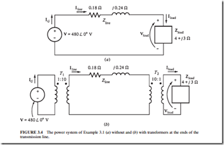
1. If the power system is exactly as described above (Fig. 3.4a), what will be the voltage at the load? What will the transmission line losses be?
2. Suppose a 1:10 step-up transformer is placed at the generator end of the transmission line and a 10:1 step-down transformer is placed at the load end of the line (Fig. 3.4b). What will the load voltage be now? What will the transmission losses be now?
Solution
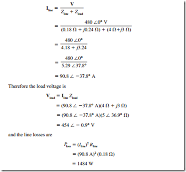
1. Figure 3.4a shows the power system without transformers. Here IG = Iline = Iload. The line current in this system is given by
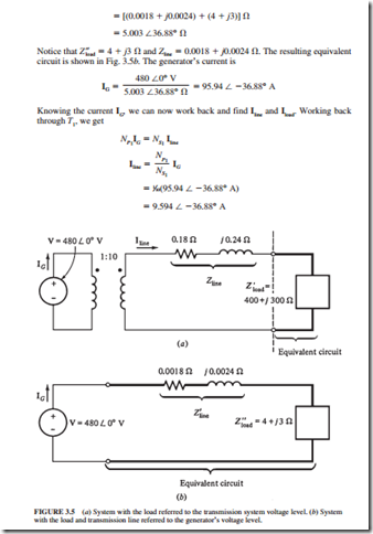
2. Figure 3.4b shows the power system with the transformers. To analyze this system, it is necessary to convert it to a common voltage level. This is done in two steps:
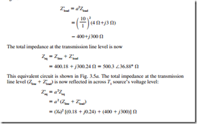
a. Eliminate transformer T2 by referring the load over to the transmission line’s volt- age level.
b. Eliminate transformer T1 by referring the transmission line’s elements and the equivalent load at the transmission line’s voltage over to the source side.
The value of the load’s impedance when reflected to the transmission system’s volt- age is
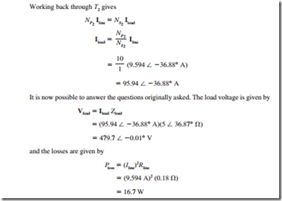
Notice that by stepping up the transmission voltage of the power system, the trans- mission losses have been reduced by a factor of 90. Also, the voltage at the load dropped significantly in the system with transformers compared to the system without transformers.
