GAS RELAY AND COLLECTION SYSTEMS
Introduction
Most utilities and large industries have a gas relay mounted on their power transformers. As mentioned earlier, gases are generated by the chemical and electrical phenomena asso- ciated with the development of faults in oil-filled transformers. A significant amount of gas is normally formed in the early stage of the fault.
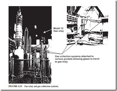
The gases generated and the air expelled from the oil by the fault rise to the top of the equipment and get collected in a gas relay. Figure 4.13 illustrates a gas collection system. It ensures that gases trapped in various pockets are allowed to escape and travel to the gas relay.
Gas Relay
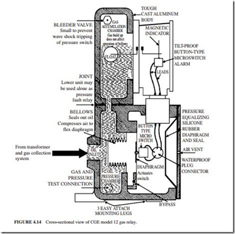
The gas detector relay (Fig. 4.14) gives an early indication of faults in oil-filled transformers. There are two types of faults:
1. Minor faults that result in a slow evolution of gases. These faults may result from the following:
● Local heating
● Defective insulation structures
BYPASS
● Improperly brazed joints
● Loose contacts
● Ground faults
● Short-circuit turns
● Opening or interruption of a phase current
● Burnout of core iron
● Release of air from oil
● Leakage of air into the transformer
2. Major faults that result in a sudden increase in pressure. These faults are normally caused by flashover between parts. The relay will detect both types of faults.
The relay has two sections:
● A gas accumulation chamber is located at the top of the relay. It consists of an oil chamber with a gas bleeder needle valve. A float in the oil chamber operates a magnetic oil gauge with an alarm switch.
● A pressure chamber is located at the bottom of the relay. It has two parts. An oil chamber is seen at the rear of the relay. The chamber is connected to the transformer by a pipe entering the back of the relay. A test valve is located at the base. It is used for making operation checks. Sensitive brass bellows separate the first section from the second.
There is an air chamber in the front. It contains stops for the bellows to prevent overtravel, a flexible diaphragm, and a microswitch. When the bellows move, they compress the air behind the diaphragm. This action actuates the microswitch which is fastened to the diaphragm. When arcing occurs in the transformer, it causes a rapid evolution of gas in the oil. A pressure wave is generated through the oil. This wave will reach the relay through the pipe. It will compress the flexible bellows. The air in the chamber is compressed by the dis- placement of the bellows. Since the air cannot pass quickly through the bypass valve, it forces the flexible diaphragm to close the contact of the trip switch. This action disconnects the transformer.
It is essential to find the fault when the pressure contact trips the transformer. The fault should be corrected before the transformer is put back in service.

