Phase Shifting the Triac
To obtain complete voltage control, the triac, like the SCR, must be phase shifted. Several methods can be used to phase shift a triac, but only one will be covered
in this unit. In Figure 63– 8, a diac is used to phase shift the triac. Resistors Rl and R2 are connected in series with capacitor C1. Resistor R1 is a variable resistor used to control the charge time of capacitor C1. Resistor R2 is used to limit current if resistor R1 is adjusted to 0 ohms. Assume that the diac connected in series with the gate of the triac will turn on when capacitor C1 has been charged to 15 volts. When the diac turns on, capacitor C1 will discharge through the gate of the triac. This permits the triac to fire, or turn on. Since the diac is a bi- directional device, it will permit a positive or negative pulse to trigger the gate of the triac.
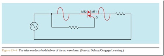
When the triac fires, there is a voltage drop of about 1 volt across MT2 and MT1. The triac remains on until the AC voltage drops to a low enough value to permit the triac to turn off. Since the phase shift circuit is connected parallel to the triac, once the triac turns on, capacitor C1 cannot begin charging again until the triac turns off at the end of the AC cycle.
Notice that the pulse applied to the gate is con- trolled by the charging of capacitor C1, not the amplitude of voltage. If the correct values are chosen, the triac can be fired at any point in the AC cycle applied to it. The triac can now control the AC voltage from 0 to the full voltage of the circuit. A common example of this type of triac circuit is the light dimmer control used in many homes.

