Piston Service
CLEANING PISTONS
When cleaning aluminum pistons, do not use a caustic solvent such as lye, washing soda, etc., as they dissolve aluminum. A caustic solvent is read ily recognized because it makes the fingers feel soapy-and if strong enough will smart and burn.
Use a stiff brush. If a wire brush is used be careful not to scratch the piston skirt or the ring grooves.
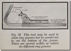
Hard carbon is best removed from the ring grooves by a special tool made for the purpose. There are a number on the market. One design is shown in Fig. 38. Be careful not to allow the tool to cut into the bottom of the groove.
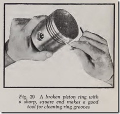
Lacking such a tool, a satisfactory ring groove cleaner, Fig. 39, can be made by breaking a piston ring in two. Square off the broken end by filing or grinding. Be sure the edge is sharp and not rounded. Insert the end of the ring in the groove and push the ring forward to clean out the groove.
On some pistons, there is a narrow groove above the top ring which acts as a heat dam to prevent too much heat flowing from head to skirt. Carbon in this groove reduces the effectiveness of the dam, so be sure to clean this groove also.
Clean out the oil drain holes in the lower grooves by running a drill through them by hand. The drill should be the same size as the holes. It is best to mount the drill in a small hand reamer chunk to use as a handle.
PISTON INSPECTION
After the pistons have been thoroughly cleaned they should be carefully examined . Look for cracks in the piston head, the ring lands and the skirts. Look for a small hole burned in the top of the piston, caused by excessive pinging. Needless to say, a piston with cracks or holes in it must be discard ed. Pistons with badly scored skirts should be scrapped.
RING LAND DIAMETER
This paragraph applies to new pistons as well as old. The ring lands should not contact the cylinder bore. If the faces of the ring lands show that they have been rubbing against the cylinder bore, the land diameters should be reduced. Land diame ters should be less than the skirt diameter by .005″ per inch of piston diameter for cast iron and .007″ for aluminum. These figures are for the two top lands. Somewhat less clearance is needed on the lower lands.
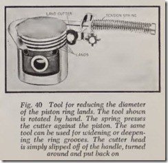
The required reduction in land diameter can be made on a lathe, a piston grinding machine, or by means of a hand tool made just for the purpose, one of which is shown in Fig. 40.
RING GROOV E CLEARANCE
Piston rings must be free in th eir grooves so that they can follow the contour of the cylinder bore. Therefore a little clearance is required.
For compression rings use .001″ per inch of bore diameter. For oil rings, .0007″ per inch of bore diameter. For a 3-inch bore, for example, the clearances are: Compression ring, .003″ (3 X
.001″); oil ring, .0021″ (3 X .0007″)-use .002″.
Ring manufacturers make a distinction between cast iron and aluminum pistons. R ing side clear ances recommended are: Aluminum piston : Top groove, .0015″ to .002″; other grooves, .001″ to
.0015″. Cast iron piston: Top groove, .002″ to
.0025″; other grooves, .0015″ to .002″.
If ring clearances are insufficient, the ring should be rubbed lightly on a piece of fine emery cloth laid on a surface plate (or piece of plate glass).
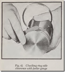
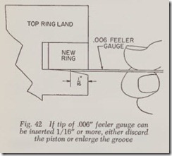
To check the clearance on worn piston s, place a new ring in the groove and measure the clearance with a .006″ feeler gauge, Fig. 41. Measure the land wear both above and below the ring. If the feeler can be inserted 1/16″ or more. Fig. 42, the piston should either be discarded or th e width of the groove enlarged to fit a wider ring (if avail able) or the same size ring can be used with a steel spacer made for the purpose .
WIDENING RING GROOVES
This operation is seldom if ever done on pas senger car engines nowadays. But in asmuch as it is sometimes performed on large, expensive truck engines, it does no harm to acquain t th e re ader of its existence.
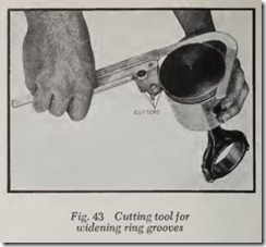
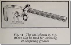
The width of the grooves may be enlarged on a lathe; or a hand tool may be used. There are several on the market. The tool shown in Fig. 43 is equipped with four widths of cutters. The cutter of the desired width is rotated into position and locked by the knurled screw. The hook-shaped end of the tool is inserted in the groove and the tool rotated by hand. Be careful to remove metal only on the sides of the groove since the tool can also be used for increasing the depth of the groove. Fig. 44 shows a somewhat similar tool.
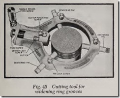
Fig. 45 illustrates another type of tool. The tongue on the three centering pins are inserted in the ring groove. The pins guide the piston. A cutter of the desired width is mounted in the cutter head and adjusted to contact the piston. Mount the piston in a piston vise or clamp the connecting rod in a vise. To cut the groove, turn the handle clocbvise. The tool is fed into the groove automatically since a worm pinion on the handle meshes with the feed screw shown. Be careful not to increase the depth of the groove unless increased groove depth is desired.
In another design, the tool not only widens the groove 1/16″ but at the same time cuts a 1/32″ slot which anchors the spacer so that it won’t rotate or float, Fig. 46.
GROOVE DEPTH FOR EXPANDER RINGS
These instructions are mainly for the installation of new rings on old pistons but note that occa sionally groove depth in new pistons will be in adequate for the rings which are to be installed. In all cases abide by the ring makers instructions on this point.
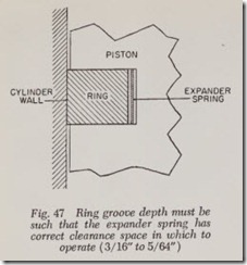
When a spring is used to expand the ring against the bore, Fig. 47, it is important that it have some working space. This space is deter mined by the depth of the groove left over after the ring is installed and the piston is placed in the cylinder bore.
If spring space is too small, the pressure on the ring may be objectionably high, forcing the ring too hard against the cylinder bore. And there is also the possibility that the overcompressed spring will break. On the other hand, if the spring space is too great, the pressure of the ring will be in adequate.
Carefully follow the instructions accompanying the rings. Generally speaking, the clearance for the expander should not be less than about .050″ (about 3/64″) nor more than .080″ (about 5/64″).
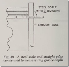
The easiest way to check this is to measure the ring groove depth and then subtract the thickness of the ring, Fig. 48. The difference approximately equals the clearance available for the expander. Place a straight edge along the skirt at right angles to the pin hole, Fig. 49, and measure the depth of the groove. Then measure the depth of the ring. The difference is the space for the spring ex pander.
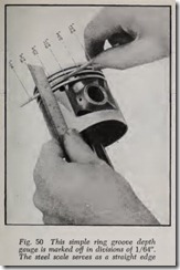
Fig. 50 shows a simple gauge for measuring ring groove depth. It is tapered from less than W’ to more than 7/32″ as shown. Use a steel scale as a straight edge and push the gauge in as far as it will readily go. Then read the gauge marking nearest the straight edge.
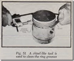
If the ring groove depth is insufficient, it can be increased by means of a ring groove tool, Fig. 51, although the piston ring maker may suggest a lighter expander spring instead. Expander springs are available in three strengths: Standard groove, shallow groove and deep groove. A deep groove spring, of course, should be used when the groove is more than .080″.
CHECK PISTON SKIRTS FOR COLLAPSE
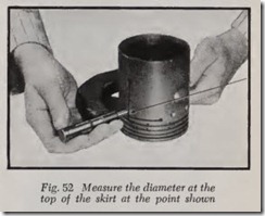
After considerable service, piston skirts, espe cially those with vertical or nearly vertical slots in them, are likely to collapse. This means that the diameter of the skirt at the bottom is slightly smaller than it was when new.
To check for this condition, measure the diameter of the skirt at top and bottom at right angles to the piston pin, Fig. 52. If the skirt is not more than .003″ smaller at the bottom than at the top, the piston may be re-used as is, but if the collapse is greater, the skirt should be expanded in a machine made for the purpose. The reason is that collapsed skirts are likely to produce objectionable piston slap. Expansion should bring the skirt back to its original diameter or perhaps .0005″ larger.
