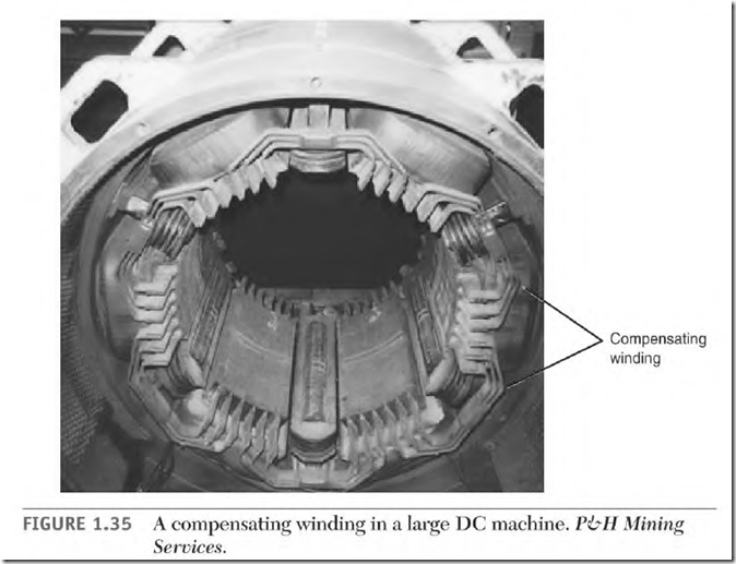
The compensating winding (Fig. 1.35) is an extension of the interpoles. It is in series with the armature and is part of the interpole circuit. It brings the effect of the interpoles out to the center of the field pole iron. (This is necessary for motors with a large bore diameter and wide load variations.) When there is a sudden load change, the interpole’s influence alone doesn’t cover enough pole area to control the arcing.
The compensating winding usually consists of a single turn (a heavy copper bar) embedded in slots (cut in the face of the field pole iron).
Because of high current, the end turns and connections of the compensating winding extend beyond the shunt field coils. Any wire carrying high current that is located across a shunt coil’s end turns will distort the coil’s magnetic field. The result will be magnetic unbalance and brush arcing.
Operation of a DC Motor
DC generators and motors are interchangeable. Their armature circuits have a large wire and very low resistance and conduct all the ampere output as a generator.
When used as a motor, the low-resistance armature circuit is connected to line voltage. Because of its low resistance, it will demand destructively high amperes. The following text explains how amperes are controlled in a motor’s armature circuit. It also compares an armature conductor generating voltage in a generator and the same conductor producing torque in a motor.
One Armature Conductor in a Generator as It Passes Two Poles
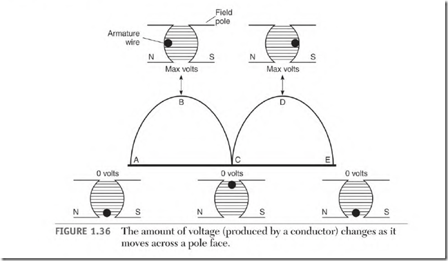
In a DC generator, the conductors of the armature cut lines of force provided by the stator fields and produce power. In Fig. 1.36, we can follow one conductor as it travels past the poles of a two-pole stator. The conductor’s voltage value changes as its position changes
Each stator pole is equal to 180 electrical degrees, making it possible to describe a location on a pole regardless of a motor’s physical size. This particular magnetic circuit consists of two poles. Together they equal 360 electrical degrees.
Figure 1.36 illustrates the voltage values produced by a conductor as it cuts the lines of force of two poles. In position A, the conductor is not cutting lines of force because it is traveling in line with them. (This is the neutral position, where no voltage is produced.) As the conductor moves toward position B, it cuts more and more lines of force, increasing its voltage. When the conductor reaches position B, it will be cutting the maximum lines of force and creating maximum voltage. The conductor is now at the 90 0 spot of the pole.
As the conductor moves toward position C, it cuts fewer and fewer lines of force until it isn’t cutting any lines of force (like position A).
As the conductor enters the south pole, it produces an opposite voltage. At this point, the commutator reverses the polarity of the conductor. The current continues to flow in the same direction as it did in position B (direct current). As the conductor moves toward position D, it cuts more and more lines of force, and its voltage increases. When it reaches position D, the voltage output again is maximum value. As the conductor moves toward position E, it cuts fewer and fewer lines of force until, like position A, position E voltage output is zero. The conductor has moved 360 electrical degrees.
One Armature Conductor in a Motor as It Passes Two Poles
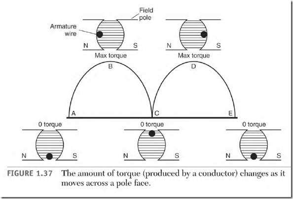
Armature conductors in a DC motor create torque. Their position (as they move across a pole face) determines how much torque is produced. The ampere demand varies with the torque produced.
Figure 1.37 illustrates the torque value that one conductor contributes as it goes by two poles. In position A, no torque is produced because the conductor is traveling in line with the lines of force. When this happens, the conductor doesn’t demand power from the line. As the conductor travels toward position B, the torque and ampere demand increase. At position B (90 0 ), both torque and amperes are at their highest value. Torque and amperes decrease as the conductor moves to point C (180 0 ).
As the conductor enters the opposite pole, the commutator reverses the direction of current flow. The conductor’s torque remains in the same direction. The torque and power demand will increase until the conductor reaches point D (270 0 , or the 90 0 spot on this pole), where it reaches its
maximum value. Torque and amperes decrease as the conductor moves to point E. At point E, the conductor will have moved 360 electrical degrees.
Counter-voltage
As the armature of a motor turns, its conductors create torque and demand amperes from the power source. A motor’s torque and ampere magnitude match a generator’s voltage magnitude at the same location on the poles, as seen in Figs. 1.36 and 1.37.
Because the armature conductors are moving in a magnetic field, they are cutting lines of force and generating voltage. The voltage they generate is opposite the polarity of the power source. This is called counter-voltage (counter electromotive force, or counter emf).
The counter-voltage value depends on the speed of the armature and the strength of the stator field. The counter-voltage generated (as the
motor’s armature rotates) cancels an equal amount of line voltage. This lowers the amount of line voltage applied to the resistance of the armature circuit.
Counter-voltage keeps the amperes in the armature circuit at a safe value. The resistance of the armature circuit is so low that, without countervoltage, the armature winding would be destroyed in a short time.
Counter-voltage Compared to Charging a Battery
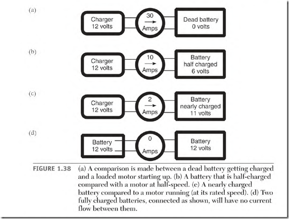
Amperes controlled by counter-voltage can be compared to a battery being charged. (When a battery charger is attached to a dead battery, high amperes flow.) High amperes flow in a DC motor (Fig. 1.38a) when the armature is stationary and line voltage is applied.
The motor in this example is designed for 100 volts and 2 amperes. The armature has 5 ohms of resistance. One hundred volts divided by 5 ohms results in 20 amperes flowing through the armature at 0 RPM.
In Fig. 1.38b the battery voltage is up to 6 volts, or is “half-charged.” Six volts in the battery cancel 6 volts of the charger, and the amperes drop. This compares to a motor turning at half-speed (Fig. 1.38b). At half-speed, the motor is generating 50 volts of counter-voltage. Fifty volts of counter-voltage cancels 50 volts from the line. Fifty volts divided by 5 ohms lowers the motor amperes to 10 amps.
Figure 1.38c shows the battery nearly charged with 11 volts. This cancels all but 1 volt of the charger, resulting in low amperes. This compares to the armature turning at its rated speed. In Fig. 1.38c, all but 10 volts are canceled
by counter-voltage. This leaves 10 volts against 5 ohms of resistance in the armature, allowing 2 amperes to flow. This is the motor’s full-load ampere rating.
If two batteries of equal charge are connected parallel (Fig. 1.38d), positive to positive and negative to negative, no amperes will flow between them. Twelve volts in one battery will cancel the 12 volts of the other.
If the motor’s armature is somehow rotated fast enough, it generates counter-voltage equal to the line voltage. At this speed, there would be no amperes flowing in the armature circuit. If the armature is rotated even faster, the motor would become a generator.


