TESTING SOLID-STATE COMPONENTS
1. Testing a Diode
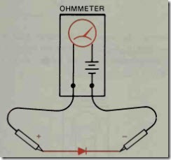
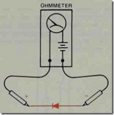
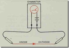
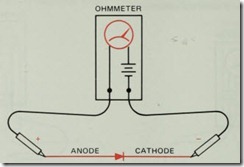
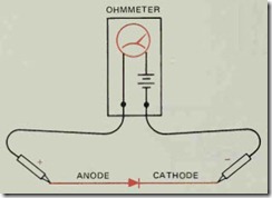
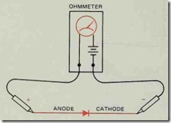
1. Connect the ohmmeter leads to the diode. No tice if the meter indicates continuity through the diode or not.
2. Reverse the diode connection to the ohmmeter.
Notice if the meter indicates continuity through the diode or not. The ohmmeter should indicate continuity through the diode in only one direction. NOTE: If continuity is not indicated in either direction, the diode is open.
If continuity is indicated in both directions, the diode is shorted.
2. Testing a Transistor
1. Using a diode, determine which ohmmeter lead is positive and which is negative. The ohmme ter will indicate continuity through the diode only when the positive lead is connected to the anode and the negative lead is connected to the cathode.
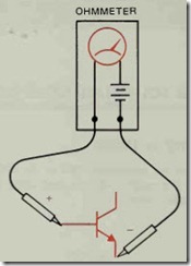
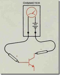
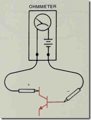
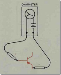
2. If the transistor is an NPN, connect the posi tive ohmmeter lead to the base and the negative lead to the collector. The ohmmeter should in dicate continuity. The reading should be about the same as the reading obtained when the diode was tested.
3. With the positive ohmmeter lead still con nected to the base of the transistor, connect the negative lead to the emitter. The ohmmeter should again indicate a forward diode junction. NOTE: If the ohmmeter does not indicate con tinuity between the base-collector or the base emitter, the transistor is open.
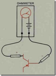
4. Connect the negative ohmmeter lead to the base and the positive lead to the collector. The ohmmeter should indicate infinity or no conti nuity.
5. With the negative ohmmeter lead connected to the base, reconnect the positive lead to the emitter. There should, again, be no indication of continuity. NOTE: If a very high resistance is indicated by the ohmmeter, the transistor is “leaky” but it may still operate in the circuit. If a very low resistance is seen, the transistor is shorted.
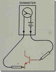
6. To test a PNP transistor, reverse the polarity of the ohmmeter leads and repeat the test. When the negative ohmmeter lead is connected to the base, a forward diode junction should be indicated when the positive lead is connected to the collector or emitter.
7. If the positive ohmmeter lead is connected to the base of a PNP transistor, no continuity should be indicated when the negative lead is connected to the collector or the emitter.
3. Testing a Unijunction Transistor
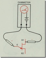
1. Using a junction diode, determine which ohmmeter lead is positive and which is negative. The ohmmeter will indicate continuity when the positive lead is connected to the anode and the negative lead is connected to the cathode.
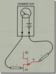
2. Connect the positive ohmmeter lead to the emitter lead and the negative lead to base # 1. The ohmmeter should indicate a forward diode junction .
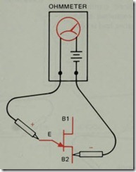
3. With the positive ohmmeter lead connected to the emitter, recon nect the negative lead to base #2. The ohmmeter should again indicate a forward diode junction.
4. If the negative ohmmeter lead is connected to the emitter, no con tinuity should be indicated when the positive lead is connected to base # 1 or base #2.
4. Testing an SCR
1. Using a junction diode, determine which ohmmeter lead is positive and which is nega tive. The ohmmeter will indicate continuity only when the positive lead is connected to the anode of the diode and the negative lead is con nected to the cathode.
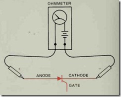
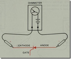
2. Connect the positive ohmmeter lead to the an ode of the SCR and the negative lead to the cathode. The ohmmeter should indicate no continuity.
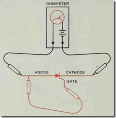
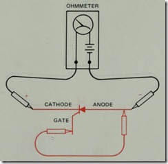
3. Using a jumper lead, connect the gate of the SCR to the anode.
The ohmmeter shou)d indicate a forward diode junction when the connection is made. NOTE: If the jumper is removed, the SCR may continue to conduct or it may turn off. This will be deter mined by whether or not the ohmmeter can supply enough current to keep the SCR above its holding current level.
4.Reconnect the SCR so that the cathode is connected to the positive ohmmeter lead and the anode is connected to the negative lead. The ohmmeter should indicate no continuity.
5. If a jumper lead is used to connect the gate to the anode, the ohmmeter should indicate no continuity. NOTE: SCRs designed to switch large currents (SO amperes or more) may indicate some leakage current with this test. This is normal for some devices.
5. Testing a Triac
1. Using a junction diode determine which ohmmeter lead is positive and which is nega tive. The ohmmeter will indicate continuity only when the positive lead is connected to the anode and the negative lead is connected to the cathode.
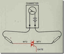
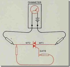
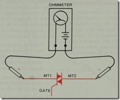
2. Connect the positive ohmmeter lead to MT2 and the negative lead to MTl. The ohmmeter should indicate no continuity through the triac.
3. Using a jumper lead, connect the gate of the triac to MT2. The ohmmeter should indicate a forward diode junction.
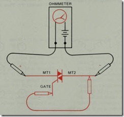
4. Reconnect the triac so that MTI is connected to the positive ohmmeter lead and MT2 is connected to the negative lead. The ohmmeter should indicate no continuity through the triac.
5. Using a jumper lead, again connect the gate to MT2. The ohmme ter should indicate a forward diode junction.
