IDENTIFYING THE LEADS OF A THREE-PHASE, WYE-CON NECTED, DUAL-VOLTAGE MOTOR
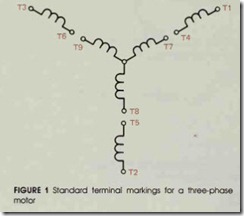
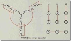
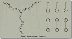
The terminal markings of a three-phase mo tor are standardized and used to connect the mo tor for operation on 240 or 480 volts. Figure # 1 shows these terminal markings and their relation ship to the other motor windings. If the motor is to be connected to a 240-volt line, the motor wind ings are connected parallel to each other as shown in figure #2. If the motor is to be operated on a 480-volt line, the motor windings are connected in series is shown in figure #3.
As long as these motor windings remain marked with the proper numbers, connecting the motor for operation on a 240- or 480-volt power line is relatively simple. If these numbers are re moved or damaged, however, the leads must be reidentified before the motor can be connected. The following procedure can be used to identify the proper relationship of the motor windings.
1. Using an ohmmeter, divide the motor wind ings into four separate circuits. One circuit will have continuity to three leads, and the other three circuits will have continuity be tween only two leads (see figure # 1).
Caution: the circuits that exhibit continuity be tween two leads must be identified as pairs, but do not let the ends of the leads touch anything.
2. Mark the three leads that have continuity with each other as T7, T8, and T9. Connect these three leads to a 240-volt, three-phase power source, figure #4. (Note: Since these windings are rated at 240 volts each, the mo tor can be safely operated on one set of wind ings as long as it is not connected to a load.)
3.With the power turned off, connect one end of one of the paired leads to the terminal marked T7. Turn the power on, and using an ac voltmeter set for a range not less than 480 volts, measure the voltage from the un connected end of the paired lead to terminals T8 and T9, figure #5. If the measured volt ages are unequal, the wrong paired lead is connected to terminal T7. Turn the power off, and connect another paired lead to T7. When the correct set of paired leads is con nected to T7, the voltage readings to T8 and T9 will be equal.
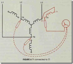
4. After finding the correct pair of leads, a de cision must be made as to which lead should be labeled T4 and which should be labeled Tl. Since an induction motor is basically a transformer, the phase windings act very similar to a multiwinding autotransformer. If terminal Tl is connected to terminal T7, it will operate similar to a transformer with its windings connected to form subtractive po larity. If an ac voltmeter is connected to T4 , a voltage of about 140 volts should be seen between T4 and T8 or T4 and T9, fig ure #6.
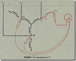
If terminal T4 is connected to T7, the winding will operate similar to a transformer with its windings connected for additive po larity. If an ac voltmeter is connected to Tl, a voltage of about 360 volts will be indicated when the other lead of the voltmeter is con nected to T8 or T9, figure #7.
Label leads Tl and T4 using the preced ing procedure to determine which lead is correct. Then disconnect and separate Tl and T4.
5. To identify the other leads, follow the same basic procedure. Connect one end of one of the remaining pairs to T8. Measure the volt age between the unconnected lead and T7 and T9 to determine if it is the correct lead pair for terminal T8. When the correct lead pair is connected to T8, the voltage between the unconnected terminal and T7 or T9 will be equal. Then determine which is TS or T2 by measuring for a high or low voltage. When TS is connected to T8, about 360 volts can be measured between T2 and T7 or T2 and T9.
6. The remaining pair can be identified as T3 or T6. When T6 is connected to T9, a volt age of about 360 volts can be measured be tween T3 and T7 or T3 and T8.
![FIGURE-4-T7-T8-and-T9-connected-to-a[2] FIGURE-4-T7-T8-and-T9-connected-to-a[2]](http://machineryequipmentonline.com/electric-equipment/wp-content/uploads/2020/04/FIGURE-4-T7-T8-and-T9-connected-to-a2_thumb.jpg)
![FIGURE--5--Measure-voltage--from--un[1] FIGURE--5--Measure-voltage--from--un[1]](http://machineryequipmentonline.com/electric-equipment/wp-content/uploads/2020/04/FIGURE-5-Measure-voltage-from-un1_thumb.jpg)
