Magnetic Theory
Figure 26.2 illustrates the path of a magnetic tape through the head assembly of a modern analogue tape recorder. The recording tape is fed from the supply reel across an initial erase head by means of the capstan and pinch roller. The purpose of the erase head is to remove any unwanted previous magnetization on the tape. Next the tape passes the record head, where the audio signal is imprinted upon it, and the playback head, in which the magnetic patterns on the tape are converted back to an audio signal suitable for subsequent amplification and application to a loudspeaker. Finally, the tape is wound onto the take-up reel. When in playback mode, the erase head and the record head are not energized. Correspondingly, in record mode, the playback head may be used to monitor the signal off-tape to ensure that recording levels and so on are correct. Less expensive cassette tape recorders combine the record and playback heads in a composite assembly, in which case off-tape monitoring while recording is not possible.
The Physics of Magnetic Recording
In a tape recording, sound signals are recorded as a magnetic pattern along the length of the tape. The tape itself consists of a polyester-type plastic backing layer, on which is applied a thin coating with magnetic properties. This coating usually contains tiny particles of ferric iron oxide (so-called ferric tapes), although more expensive tapes may use chromium dioxide particles or metal alloy particles, which have superior magnetic properties (so-called chrome or metal tapes, respectively).
The properties of magnetic materials take place as a result of microscopic magnetic domains—each a tiny bar magnet—within the material. In an unmagnetized state, these domains are effectively aligned randomly so that any overall, macroscopic magnetic external field is canceled out. Only when the ferrous material is exposed to an external magnetic field do these domains start to align their axis along the axis of the applied field, the fraction of the total number of domains so aligned being dependent on the strength of the externally applied field. Most significantly, after the external field has been removed, the microscopic domains do not altogether return to their preordered state and the bulk material exhibits external magnetic poles.
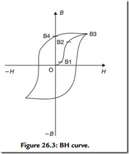
The relation between the magnetizing field (H) and the resultant induction (B) in an iron sample (assumed, initially, to be in a completely demagnetized condition) may be plotted as shown in Figure 26.3. Tracing the path from the origin, note that the first section of the looped curve rises slowly at first (between O and B1), then more rapidly (between B1 and B2), and finally more and more gradually as it approaches a point where only a very few magnetic domains remain left to be aligned. At this point (B3) the ferrous material is said to be saturated. Significantly, when the magnetizing force (H) is reduced, the magnetic induction (B) does not retrace its path along the curve B3–B2–B1–O, instead it falls along a different path, B3–B4, at which point the magnetizing force is zero again, but the
ferrous material remains magnetized with the residual induction B4. This remaining force is referred to as remnance. For this remnance to be neutralized, an opposite magnetic force must be applied, which accounts for the rest of the looped curve in Figure 26.3.
The magnitude of the applied magnetic force required to reduce the remnance to zero is termed coercivity (the ideal magnetic tape exhibiting both high remnance and high coercivity).
