Stepping Motors for Position Control Applications
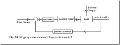
When stepping motors are used for position control applications, they can be operated in open loop. The danger is that the stepping motors may lose steps when they have to be moved several steps. In open loop, the switching rate must be sufficiently small so that correct positioning is achieved. To overcome this problem, they must be operated in closed loop. The output position is usually measured by a position
encoder and the information about the output position is fed back to the controller. The required position is compared with output position and with respect to the error the switching rate is applied. In this mode, the loss of steps is avoided. This is shown in block diagram form in Fig. 5.8.
Although the input and output positions are in digital form, they can be written in analogue form. The controller output may be written as
V is the output voltage which determines the switching rates. K is the gain and θi, θo are the demand and actual output position. When the stepping motor is energized at a specific switching rate then the voltage equation assuming with inductance L may be written as
It should be noted that for stepping motors there is no internal velocity feedback. This means that the damping ratio in stepping motors are less than that of DC servo
motors. Therefore, the stability of stepping motors must carefully investigated. The torque equation similar to DC servo motors becomes
![]() The equation of motions for rotor and load are similar to that described for DC servo motors. The reader is encouraged to obtain a catalogue from stepping motor’s manufacturer and study the dynamic behavior of stepping motors in closed position control applications at various complexities. The effect of velocity feedback which is easily available must be studied. For more complex applications, the state variables feedback as described in DC servo motors should also be investigated.
The equation of motions for rotor and load are similar to that described for DC servo motors. The reader is encouraged to obtain a catalogue from stepping motor’s manufacturer and study the dynamic behavior of stepping motors in closed position control applications at various complexities. The effect of velocity feedback which is easily available must be studied. For more complex applications, the state variables feedback as described in DC servo motors should also be investigated.

