Principal Operation
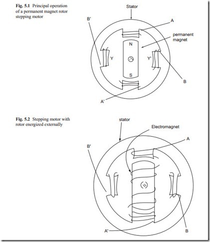
A stepping motor is defined as a rotary device whose output shaft moves in discrete steps when excited from a switched DC supply. Stepping motors are very practical devices for converting digital pulse inputs into analogue shaft-output (or rotary) motion as required in modern electric or electronic equipment. Each shaft revolution can be expressed in terms of a number of discrete identical steps or increments. Each step can be triggered by a single pulse. Stepping motors can be made with a rotor made of permanent magnets or DC energized. In the latter case, brushes must be used to energize the rotor. The principal operation of both types are shown in Fig. 5.1.
Figure 5.1 shows that when the phase A–A′ are energized, the rotor remains 0 at the position shown in the figure. When the phase A–A′ are de-energized and the phase B–B′ are energized, the rotor moves 90° (one step). The process may be repeated to move the rotor one more step of 90°. If the two phases are energized simultaneously, the rotor moves 45°. By proper sequence of energizing and de- energizing steps of 45 or 90° may be achieved.
The rotor may be designed so that magnetic poles can be achieved from external power supply. This is shown in Fig. 5.2.
Stepping motors with rotor energized externally must have brushes to supply power to a rotating rotor. Brushes need to be checked periodically for proper operation. For this reason, in servo control system permanent magnet rotor is preferred.
The stator of the stepping angles may be made with two, three, or four phases. This is shown in Fig. 5.3 Figure 5.3 shows that by properly energizing and de-energizing the phases, step angle of 60° is achieved. The rotor can be just laminated steels or permanent magnet. If the rotor is made of permanent magnet, a larger output torque can be achieved.
