STEADY-STATE CHARACTERISTICS – IDEAL (CONSTANT-CURRENT) DRIVE
In this section, we will look at how the motor would perform if it were supplied by an ideal drive circuit, which turns out to be one that is capable of supplying rectangular pulses of current to each winding when required, and regardless of the stepping rate. Because of the inductance of the windings, no real drive circuit will be able to achieve this, but the most sophisticated (and expensive) ones achieve near-ideal operation up to very high stepping rates.
Requirements of drive
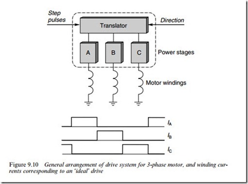
The basic function of the complete drive is to convert the step command input signals into appropriate patterns of currents in the motor windings. This is achieved in two distinct stages, as shown in Figure 9.10, which relates to a 3-phase motor.
The ‘translator’ stage converts the incoming train of step command pulses into a sequence of on/oV commands to each of the three power stages. In the one-phase-on mode, for example, the Wrst step command pulse will be routed to turn on phase A, the second will turn on phase B and so on. In a very simple drive, the translator will probably provide for only one mode of operation (e.g. one-phase-on), but most commercial drives provide the option of one-phase-on, two-phase-on and half stepping. Single-chip ICs with these three operating modes and with both three-phase and four-phase outputs are readily available.
The power stages (one per phase) supply the current to the windings. An enormous diversity of types are in use, ranging from simple ones with one switching transistor per phase, to elaborate chopper-type circuits with four transistors per phase, and some of these are discussed in Section 9.5. At this point, however, it is helpful to list the functions required of the ‘ideal’ power stage. These are Wrstly that when the translator calls for a phase to be energised, the full (rated) current should be established immediately; secondly, the current should be maintained constant (at its rated value) for the duration of the ‘on’ period and Wnally, when the translator calls for the current to be turned oV, it should be reduced to zero immediately.
The ideal current waveforms for continuous stepping with one- phase-on operation are shown in the lower part of Figure 9.10. The currents have a square proWle because this leads to the optimum value of running torque from the motor. But because of the inductance of the windings, no real drive will achieve the ideal current waveforms, though many drives come close to the ideal, even at quite high stepping rates. Drives which produce such rectangular current waveforms are (not surprisingly) called constant-current drives. We now look at the running torque produced by a motor when operated from an ideal constant- current drive. This will act as a yardstick for assessing the performance of other drives, all of which will be seen to have inferior performance.
Pull-out torque under constant-current conditions
If the phase currents are taken to be ideal, i.e. they are switched-on and switched-oV instantaneously, and remain at their full-rated value during each ‘on’ period, we can picture the axis of the magnetic Weld to be advancing around the machine in a series of steps, the rotor being urged to follow it by the reluctance torque. If we assume that the inertia is high enough for Xuctuations in rotor velocity to be very small, the rotor will be rotating at a constant rate, which corresponds exactly to the stepping rate.
Now if we consider a situation where the position of the rotor axis is, on average, lagging behind the advancing Weld axis, it should be clear that, on average, the rotor will experience a driving torque. The more it lags behind, the higher will be the average forward torque acting on it, but only up to a point. We already know that if the rotor axis is displaced too far from the Weld axis, the torque will begin to diminish, and eventually reverse, so we conclude that although more torque will be developed by increasing the rotor lag angle, there will be a limit to how far this can be taken.
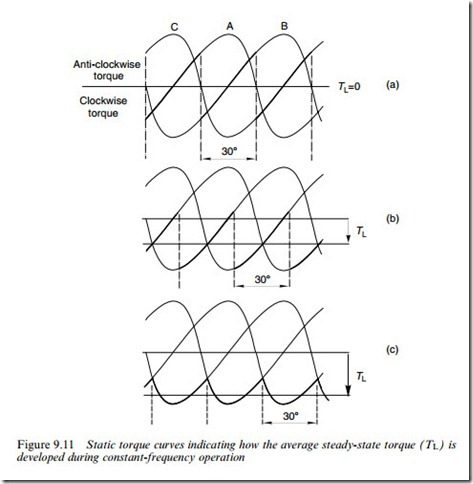
Turning now to a quantitative examination of the torque on the rotor, we will make use of the static torque–displacement curves discussed earlier, and look at what happens when the load on the shaft is varied, the stepping rate being kept constant. Clockwise rotation will be studied, so the phases will be energised in the sequence ABC. The instantaneous torque on the rotor can be arrived at by recognising (a) that the rotor speed is constant, and it covers one-step angle (308) between step com- mand pulses, and (b) the rotor will be ‘acted on’ sequentially by each of the set of torque curves.
When the load torque is zero, the net torque developed by the rotor must be zero (apart from a very small torque required to overcome friction). This condition is shown in Figure 9.11(a) . The instantaneous torque is shown by the thick line, and it is clear that each phase in turn exerts Wrst a clockwise torque, then an anticlockwise torque while the rotor angle turns through 308. The average torque is zero, the same as the load torque, because the average rotor lag angle is zero.
When the load torque on the shaft is increased, the immediate eVect is to cause the rotor to fall back in relation to the Weld. This causes the clockwise torque to increase, and the anticlockwise torque to decrease. Equilibrium is reached when the lag angle has increased suYciently for the motor torque to equal the load torque. The torque developed at an intermediate load condition like this is shown by the thick line in Figure 9.11(b). The highest average torque that can possibly be developed is shown by the thick line in Figure 9.11(c): if the load torque exceeds this value (which is
known as the pull-out torque) the motor loses synchronism and stalls, and the vital one-to-one correspondences between pulses and steps are lost.
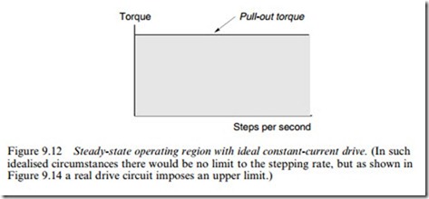
Since we have assumed an ideal constant-current drive, the pull-out torque will be independent of the stepping rate, and the pull-out torque– speed curve under ideal conditions is therefore as shown in Figure 9.12. The shaded area represents the permissible operating region: at any particular speed (stepping rate) the load torque can have any value up to the pull-out torque, and the motor will continue to run at the same speed. But if the load torque exceeds the pull-out torque, the motor will suddenly pull out of synchronism and stall.
As mentioned earlier, no real drive will be able to provide the ideal current waveforms, so we now turn to look brieXy at the types of drives in common use, and at their pull-out torque–speed characteristics.


